


S3C8275X/F8275X/C8278X/F8278X/C8274X/F8274X TIMER 1
11-1
11 TIMER 1
ONE 16-BIT TIMER MODE (TIMER 1)
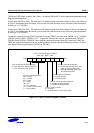
The 16-bit timer 1 is used in one 16-bit timer or two 8-bit timers mode. If TACON.7 is set to "1", timer 1 is used as
a 16-bit timer. If TACON.7 is set to "0", timer 1 is used as two 8-bit timers.
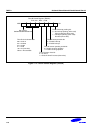
• One 16-bit timer mode (Timer 1)
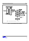
• Two 8-bit timers mode (Timer A and B)
OVERVIEW
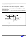
The 16-bit timer 1 is a 16-bit general-purpose timer. Timer 1 has the interval timer mode by using the appropriate
TACON setting.
Timer 1 has the following functional components:
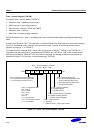
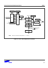
• Clock frequency divider (fxx divided by 512, 256, 64, 8, or 1, fxt, and T1CLK: External clock) with multiplexer
• 16-bit counter (TACNT, TBCNT), 16-bit comparator, and 16-bit reference data register (TADATA, TBDATA)
• Timer 1 match interrupt (IRQ 0, vector F0H) generation
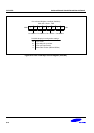
• Timer 1 control register, TACON (set 1, bank 1, E6H, read/write)
FUNCTION DESCRIPTION
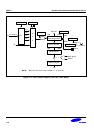
Interval Timer Function
The timer 1 module can generate an interrupt, the timer 1 match interrupt (T1INT). T1INT belongs to the interrupt
level IRQ 0, and is assigned a separate vector address, F0H.
The T1INT pending condition should be cleared by software after IRQ 0 is serviced. The T1INT pending bit must
be cleared by the application sub-routine by writing a "0" to the TACON.0 pending bit.
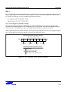
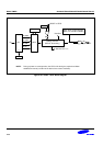
In interval timer mode, a match signal is generated when the counter value is identical to the values written to the
timer 1 reference data registers, TADATA and TBDATA. The match signal generates a timer 1 match interrupt
and clears the counter.
If, for example, you write the value 32H and 10H to TADATA and TBDATA, respectively, and 8EH to TACON, the
counter will increment until it reaches 3210H. At this point, the timer 1 interrupt request is generated, the counter
value is reset, and counting resumes.