Unit 3: Installation
S8400 Series Operator Manual
3-21 PN: 9001160B
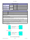
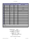
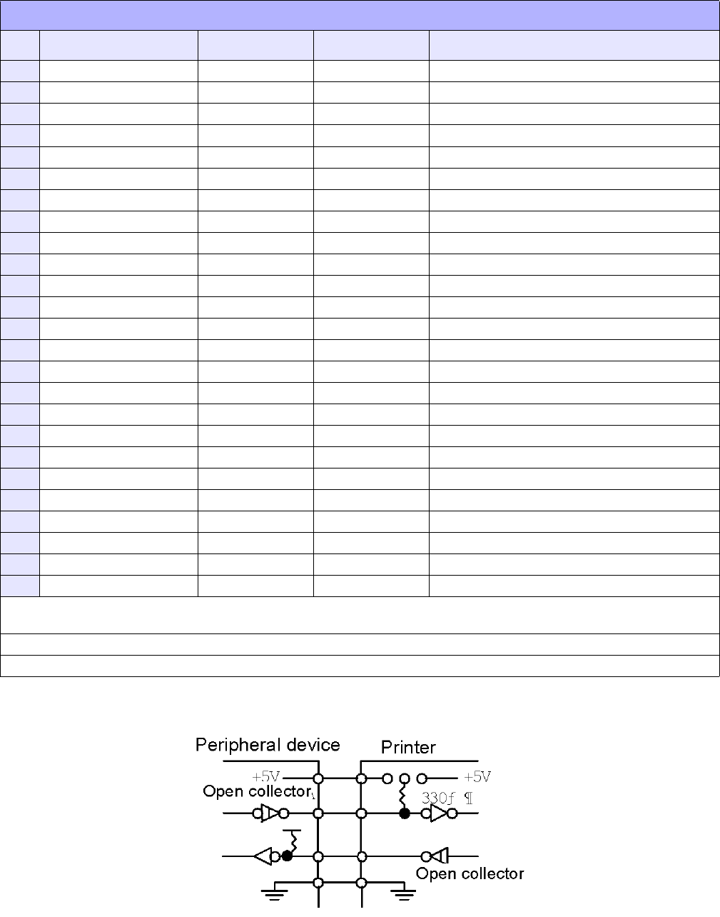
Figure 3-12, Input/Output Circuit Diagram
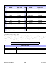
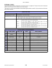
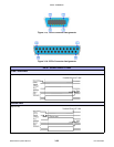
25-PIN CONNECTOR ASSIGNMENTS
PIN SIGNAL NAME DIRECTION LEVEL MAX CURRENT
1 Frame Ground --- --- ---
2 +5V --- --- ---
3 --- --- --- ---
4 Machine Error Output Low 5V, 400mA
5 Print End (PREND) Output Low 5V, 400mA
6 Online Output Low 5V, 400mA
7 --- --- --- ---
8 Reprint (PRIN2) Input Low High: high impedance, Low: -15mA or more, 0V
9 --- --- --- ---
10 --- --- --- ---
11 EXT_GND --- --- ---
12 +5V --- --- ---
13 +24V --- --- ---
14 GND --- --- ---
15 EXT_GND --- --- ---
16 Ribbon End Output High 5V, 400mA
17 Paper End Output Low 5V, 400mA
18 Ribbon Near End Output High 5V, 400mA
19 --- --- ---
20 Print Start (PRIN) Input Low High: high impedance, Low: -15mA or more, 0V
21 --- --- --- ---
22 --- --- --- ---
23 --- --- --- ---
24 EXT5V_IN Input --- 5V
25 GND --- --- ---
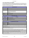
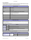
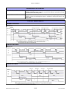
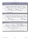
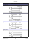
Choose from Type I to Type IV for PREND (the output signal for Pin 5). PREND will not be output when the command is “0” in
the cutter mode.
Connect EXT_GND (Pins 11, 15) to external equipment GND.
Supply EXT5V_IN (Pin 24) 5V from the external power supply.


