Unit 3: Installation
SATO HT200e Operator Manual PN 9001103B Page 3-5
INTERFACE SELECTION
The HT200e has two integrated interface connectors accessible on the printer’s left front side.
One is a RS232C serial used for interfacing with a host computer and the other is for use with an
optional scanner to input variable data by reading barcode symbols from a menu sheet.
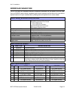
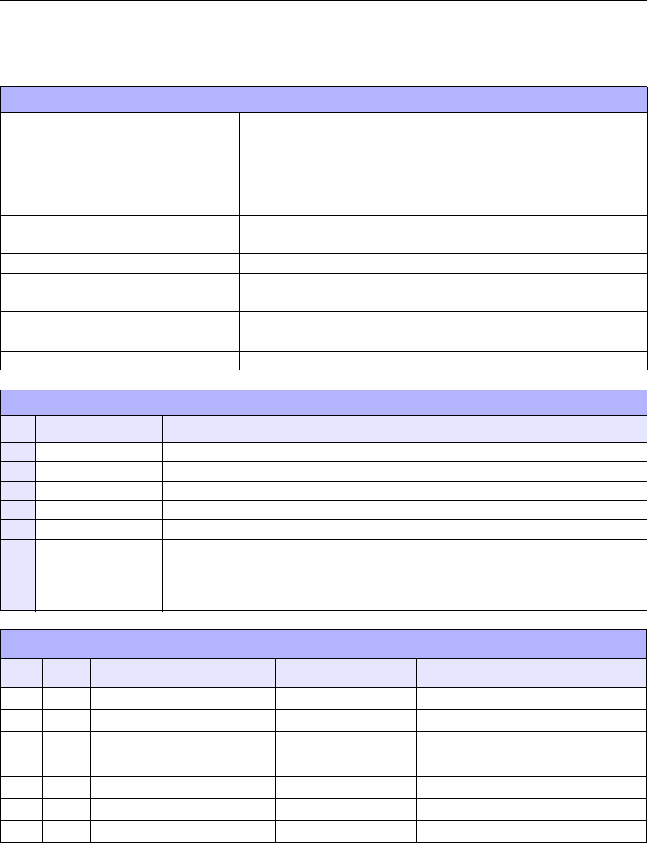
RS232C SERIAL INTERFACE SPECIFICATIONS
Asynchronous ASCII Half-duplex communication
Ready/Busy Hardware Flow Control
Pin 9, DTR Control
Pin 4, RTS Error Condition
X-On/X-Off Software Flow Control
Bi-Directional Communication
Data Transmission Rate 4800, 9600, 19200 bps
Data Length 8 bit (selectable)
Stop Bit 1 or 2 bits (selectable)
Parity Bit ODD, EVEN, NONE (selectable)
Character Format 1 Start Bit (fixed), 7 or 8 bits (selectable)
Connector DB9S (female)
Cable DB-9P (male), 50 feet maximum length.
Signal Levels High = +5V to +12V, Low = -5V to -12V
RS232 INTERFACE SIGNALS
PIN DIRECTION SIGNAL DEFINITION
1 Reference FG (Frame Ground)
2 To Host TD (Trnasmit Data) - Data from the printer to the host computer. X-On/X-Off.
3 To Printer RD (Receive Data) - Data to the printer from the host computer.
4 To Host RTS (Request To Send) - Always high.
6 To Printer DSR (Data Set Ready) Always high.
7 Reference SG (Signal Ground)
9 To Host DTR (Data Terminal Ready) - This signal applies to Ready/Busy flow control.
The printer is ready to receive data when this pin is high. It goes low when the
printer is Busy or off line due to an error condition.
RS232 CABLE REQUIREMENTS
DB9 DB25 HOST CONNECTION DB9 PRINTER
1 FG (Frame Ground) Bi-Directional 1 FG (Frame Ground)
2 3 RD (Receive Data) To Host 2 TD (Transmit Data)
3 2 TD (Transmit Data) To Printer 3 RD (Receive Data)
8 5 CTS Clear To Send) To Printer DB9 - 6 4 RTS (Request to Send)
4 20 DTR (Data Terminal Ready) To Printer DB9 - 4 6 DSR (Data Set Ready)
6 6 DSR (Data Set Ready) To host 9 DTR (Data Terminal Ready)
5 7 SG (Signal Ground) Bi-Directional 7 SG (Signal Ground)


