Unit 6: Maintenance
SATO HT200e Operator Manual PN 9001103A Page 6-5
ADJUSTMENT PROCEDURES
This printer incorporates a series of sub-assemblies that, in conjunction, comprise the total
printer assembly. Many of these sub-assemblies are designed to be adjustable to maintain
optimum performance of the printer throughout its life. This chapter of the Operator Manual
addresses the proper technique for their adjustment.
It may be necessary to refer to this chapter following component replacement. Use the relative
procedure in that chapter to replace the component, test cycle the printer, and then adjust as
necessary in accordance to the relative procedures in this chapter.
PRINT HEAD ALIGNMENT
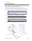
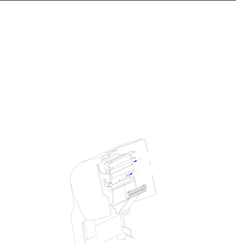
The print head may require alignment following its replacement. Poor alignment of the print head
with the platen roller will result in print that will drift from one side toward the opposite side. To
achieve print that is perpendicular with the media, slightly loosen the two screws securing the
print head mounting bracket to the top frame assembly and alter the position of the print head
until it appears to perfectly aligned with the upper perimeter of the top frame assembly. Retighten
the two screws with the print head held in that position, then test print labels to ensure a proper
alignment.
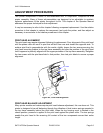
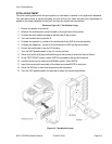
Figure 6-2, Print Head Alignment
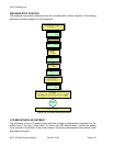
PRINT HEAD BALANCE ADJUSTMENT
Many printer models and makes require print head balance adjustment, this one does not. This
printer is designed to be self balancing through the utilization of dual torsion springs mounted in
the top frame assembly behind the print head. When the top housing cover is latched in the
closed position, pressure is applied to the print head against the platen roller. The two springs
enable the print head to flex ensuring full contact of the two components across their entire
length.
Screw x2
Print Head


