


Momentus Installation Guide
ST94011A, ST94811A, ST92011A, and ST92811A
ATA Interface Disc Drives
Publication Number: 100271723, Rev. B, April 2004
The easiest way to install your drive
Many of today’s mobile computers have been designed to make it possible
for the end user to replace the hard drive. Refer to your system’s user man-
ual for the location of the hard drive compartment and the specific instruc-
tions regarding replacement.
Some mobile systems are sealed and require specialized tools to gain
access to the hard drive.
Caution. Special training or tools may be needed to service some mobile
computers. In some cases, opening the case may void your war-
ranty. Consult your system documentation.
Seagate recommends taking your system to an authorized service techni-
cian to replace your hard drive.
Refer to your system manufacturer’s support website for the most up-to-
date information. Read and follow all instructions regarding the proper
steps to be taken when replacing the systems hard drive.
What you need
• A Phillips screwdriver
• Existing drive mounting screws (reuse)
• Existing drive mounting framework, cage or tray (reuse)
• ATA interface adapter (built into notebook and laptop systems)
Handling precautions/electrostatic discharge protection
• Disc drives are fragile. Do not drop or jar the drive. Handle the drive only
by the edges or frame. Keep the drive in the electrostatic discharge
(ESD) bag until you are ready to install it to minimize handling damage.
• Drive electronics are extremely sensitive to static electricity. While
installing the drive, wear a wrist strap and cable connected to ground.
• Turn off the power to the host system during installation.
• Do not disassemble the drive. Doing so voids the warranty. See the war-
ranty information on page 2.
• Do not apply pressure or attach labels to the circuit board or to the top of
the drive.
Drive characteristics
ST94011A ST92011A
Formatted capacity 40 Gbytes 20 Gbytes
Total number of sectors* 78,140,160 39,070,080
Cache size 2 Mbytes 2 Mbytes
ST94811A ST92811A
Formatted capacity 40 Gbytes 20 Gbytes
Total number of sectors* 78,140,160 39,070,080
Cache size 8 Mbytes 8 Mbytes
*One sector equals 512 bytes.
Replacing the existing hard drive
Each system has its own unique hard drive compartment. Refer to your
system manual to locate the hard drive compartment and for instructions
on removing and replacing the hard drive.
Warning. Turn off the computer. If you have a notebook or laptop com-
puter, disconnect the power charger/adapter and remove the
battery before you open the case or touch any internal compo-
nents.
Note. This drive is designed for a host computer that supplies interface
signals and +5V power through a single 44-pin connector. Most
mobile computers have a fixed connector that attaches directly to
the drive.
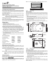
Setting the jumpers
Refer to the jumper settings in Figure 1 or on your drive label to configure
the drive for your system. Jumper settings can also be accessed online
from our web site at www.sea
gate.com.
Master or single drive: Use the options jumper block shown in Figure 1 to
configure the drive for operation. This jumper block is the 4-pin header
adjacent to pins 1 and 2 of the I/O signal pins.
Note. For mobile system operation, use cable select (default) or master.
Figure 1. Jumper settings
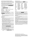
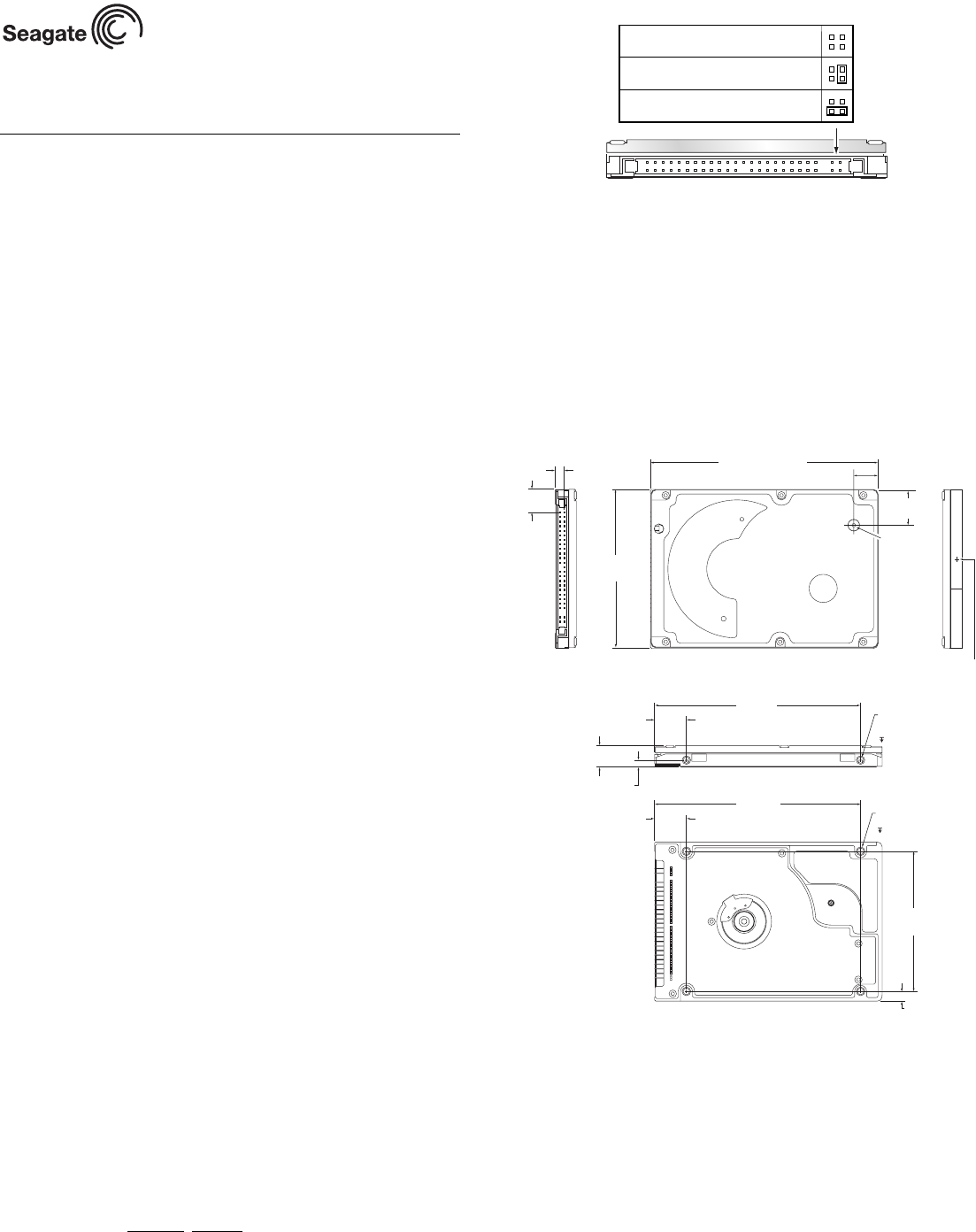
Drive mounting
You can mount the drive using four screws in the side-mounting holes or
four screws in the bottom-mounting holes. See Figure 2 for drive mounting
dimensions. Follow these important mounting precautions when mounting
the drive:
• Allow a minimum clearance of 0.030 inches (0.76 mm) around the entire
perimeter of the drive for cooling.
• Use only M3 UNC mounting screws. (Reusing the existing screws may
be acceptable provided the maximum screw penetration depth of 0.098
inches is not exceeded.)
• Gently tighten the mounting screws (maximum torque: 4.0 in-lb).
• Four (4) threads (0.080 inches) minimum screw engagement recom-
mended.
Figure 2. Mounting dimensions—end, top, side, and bottom views
Configuring the BIOS
After completing the drive installation, restart your computer. Your com-
puter may automatically detect your new drive. If your computer does not
automatically detect your new drive, follow the steps below.
1. Restart your computer. While the computer restarts, run the system
setup program (sometimes called BIOS or CMOS setup). This is usu-
ally done by pressing a special key, such as DELETE, ESC, or F1 dur-
ing the startup process.
2. Within the system setup program, instruct the system to auto detect
your new drive.
3. Save the settings and exit the setup program.
When your computer restarts, it should recognize your new drive. If your
system still doesn’t recognize your new drive, see the troubleshooting
section on this sheet.
Drive is slave
Drive is master (or single drive)
Cable select
.157
(3.9878)
.399
(10.135)
3.945 +/-0.0098
(100.2 +/-.25)
2.750 +/- .0098
(69.85 +/- .25)
2X M3 X 0.5-6H
Mounting holes
Both sides
.12 min. full thread
4X M3 X 0.5-6H
Mounting holes
.10 min. full thread
3.567
(90.602)
.551
(13.99)
3.567
(90.60)
.551
(13.99)
2.430
(61.722)
.160
(4.06)
2X .118
Both sides
.374 +/- .0078
(9.5 +/- .2)
inches
(mm)
Recommended case
temp. measurement location
Breather Hole
Do not cover
or seal.
0.680 +/- .010
(17.27 +/- .254)
0.490 +/- .010
(12.446 +/- .254)