


value to 0. Make a copy (100%) again.
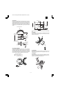
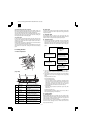
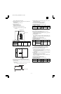
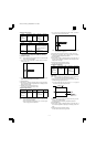
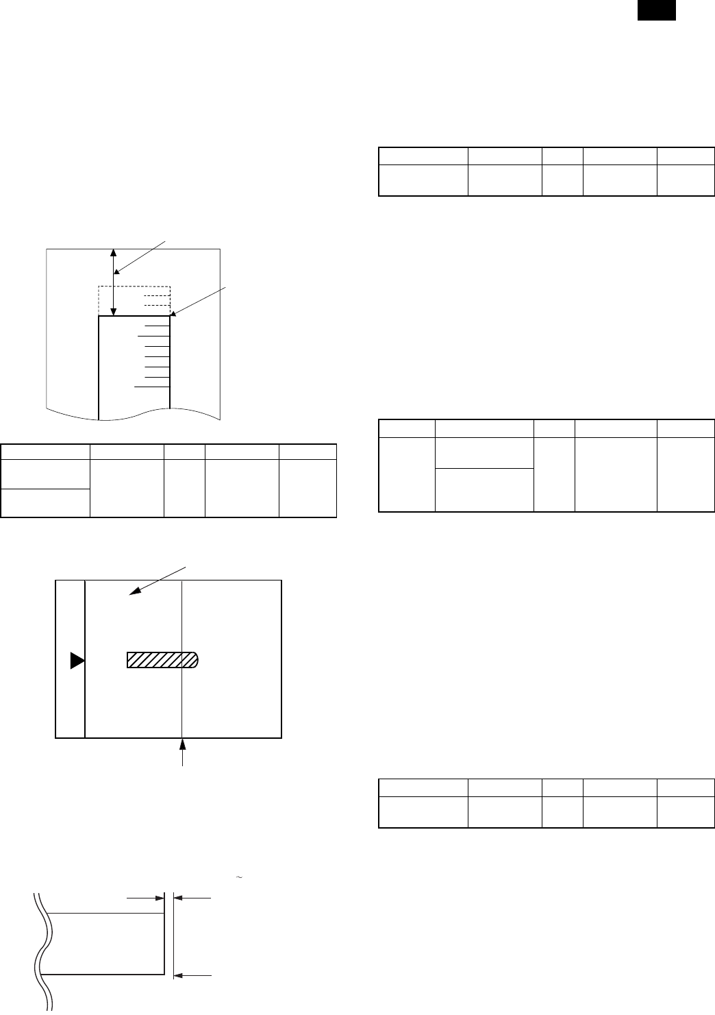
5) Set the laser radiation timing (image loss amount). Measure R in
the figure below.
Laser radiation timing = R (mm) × 10
6) Set the lead edge void.
Measure H in the figure below.
Lead edge void = H(mm) × 10
7) Enter the set value and press the start key.
The correction value is stored and a copy is made.
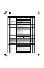
<Adjustment specification>
Mode Specification SIM Set value Set range
Laser radiation
timing
1 ~ 4mm SIM
45-1
1 step:
0.1mm shift
1 ~ 99
Lead edge void
adjustment
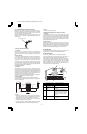
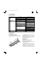
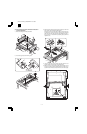
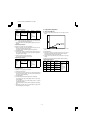
b. Rear edge void adjustment
1) Set a scale as shown in the figure below.
2) Set the document size to A4, and make two copies at 100%.
3) Check the second copy. If necessary, perform the following ad-
justment procedure.
* The first copy does not show the void. Be sure to check the
second copy.
4) Execute SIM 50-1 and set the density mode to AE + TEXT +
PHOTO (Rear edge void).
The currently set adjustment value is displayed.
5) Enter the set value and press the start key.
The correction value is stored and a copy is made.
<Adjustment specification>
Mode Specification SIM Set value Set range
Rear edge void 4mm or less SIM
50-1
1 step:
0.1mm shift
1-99
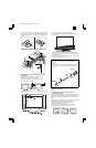
c. Paper off center adjustment
1) Execute SIM 50-1 and set the density mode of Manual (TEXT)
(Left edge void) to 0.
2) Set a test chart (UKOG-0089SCZZ) on the document table.
3) Select a paper feed port and make a copy.
Compare the copy and the test chart. If necessary, perform the
following adjustment procedure.
4) Execute SIM 50-10.
After completion of warmup, shading is performed and the cur-
rently set off center adjustment value of each paper feed port is
displayed.
5) Enter the set value and press the start key.
The correction value is stored and a copy is made.
<Adjustment specification>
Mode Specification SIM Set value Set range
Paper
off center
Single:
Center ±2.0mm
SIM
50-10
Add 1: 0.1mm
shift to R side.
Reduce 1:
0.1mm shift to
L side.
1 ~ 99
Duplex:
Center ±2.5mm
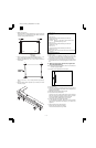
d. Left edge void area adjustment
Note: Before performing this adjustment, be sure to check that the
paepr off center adjustment (SIM 50-10) is completed.
1) Set a test chart (UKOG-0089SCZZ) on the document table.
2) Select a paper feed port and make two copies.
Compare the second copy and the test chart. If necessary, per-
form the following adjustment procedure.
* The first copy does not show the void. Be sure to check the
second copy.
3) Execute SIM 50-1 and set the density mode to Manual (TEXT)
(Left edge void).
The currently set adjustment value is displayed.
(When the off center adjustment previously described is per-
formed, "0" is displayed.)
4) Enter the set value and press the start key.
The correction value is stored and a copy is made.
<Adjustment specification>
Mode Specification SIM Set value Set range
Left edge void 1 ~ 4mm SIM
50-1
1 step:
0.1mm shift
1 ~ 99
* When the left edge void is set with the paper off center adjusted,
the both edge void is automatically adjusted.
5mm
10mm
(Example)
Lead edge void H
Image loss R
A4(8.5" x 11")
Paper rear edge
Scale image
Paper rear edge
Void amount (Standard value: 0
4mm)
AR-161
AR-160/161 FM/E [7] ADJUSTMENT 11/27/1998
7 – 3