


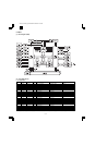

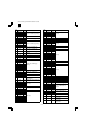


Pin No. Pin name Signal name I/O Function Purpose Descriptions
74 P25 /FAXPAGE IN General port 25 FAX option page signal
detection
0: Page effective
75 P24 /READY OUT General port 24 Machine ready signal L: Machine ready state
76 P23 /PWOFF OUT General port 23 Power off signal L: Power interruption
detecting state
77 P22 /SCANSP OUT General port 22 Scan stop signal L: Scanning operation
interruption
78 P21 /SCANST OUT General port 21 Scan start signal L: Scanning operation
effective
79 P20 /PRSTART OUT General port 20 Print start signal L: Printing effective
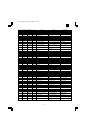
80 /WDTOVR — OUT Watch dog timer overflow System reset L: System restart
81 /RES — IN System reset System reset 0: Power on reset
82 NMI — IN Non-maskable interruption
request
Reservation 1: Level fixing input
83 /STBY — IN Stand-by Reservation 1: Level fixing input
84 VCC POW Power pin
85 XTAL — IN Oscillation pin Oscillator (19.6608MHz)
86 EXTAL — OUT Oscillation pin Oscillator (19.6608MHz)
87 VSS POW Ground pin
88 â CPUCLK OUT System clock System clock 19.6608MHz clock output
89 VCC POW Power pin
90 /AS /AS OUT Address strobe System bus L: Address effective
91 /RD /RD OUT Lead strobe System bus L: Lead effective
92 /HWR /HWR OUT Highlight enable System bus L: Highlight effective
93 /LWR /LWR OUT Row write enable System bus L: Row write effective
94 PF2 /TMEN OUT General port F2 Toner motor drive control L: Rotating
95 PF1 PMD OUT General port F1 Polygon motor drive control H: Rotating
96 PF0 MMD OUT General port F0 Main motor drive control H: Rotating
97 P50 /MMRDY IN General port 50 Main motor ready signal 0: Rotation stable state
98 P51 /PMRDY IN General port 51 Polygon motor ready signal 0: Rotation stable state
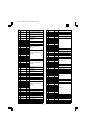
99 VSS POW Ground pin
100 VSS POW Ground pin
101 P52 /PRLINE OUT General port 52 Print line signal L: Printing effective
102 P53 /SCLINE OUT General port 53 Scan line signal L: Scanning operation
effective
103 AVCC POW Analog power pin
104 VREF POW Analog reference pin
105 AN0 RTH IN Analog input 0 Fusing thermistor
temperature detection
106 AN1 — IN Analog input 1 Reservation
107 AN2 — IN Analog input 2 Reservation
108 AN3 TONER IN Analog input 3 Toner sensor 5V: Toner empty
109 AN4 — IN Analog input 4 Reservation
110 AN5 — IN Analog input 5 Reservation
111 DA0 DA0 OUT Analog output 0 CCD reference + side
112 DA1 DA1 OUT Analog output 1 CCD reference – side
113 AVSS POW Analog ground pin
114 VSS POW Ground pin
115 TCLKD LFTCLK IN Timer clock external input Separator motor step count Separator motor clock input
116 TIOCA2 TMCLK OUT Timer clock external output Toner motor clock 960Hz clock output
117 TCLKC SFTCLK IN Timer clock external input Shifter motor step count Shifter motor clock input
118 TIOCA1 PMCLK OUT Timer clock external output Polygon motor clock 2078.74Hz clock output
119 TCLKB SPFCLK IN Timer clock external input SPF motor step count SPF motor clock input
120 TCLKA MIRCLK IN Timer clock external input Mirror motor step count Mirror motor clock input
121 /DACK1 — OUT DMAC channel 1
acknowledge
Reservation L: Acknowledge effective
122 /DACK0 — OUT DMAC channel 0
acknowledge
Reservation L: Acknowledge effective
123 MD0 — IN Operation mode setting pin 0 Operation mode setting
(MODE 4)
Operation mode 4
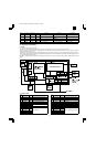
(Pin descriptions) IN: Input pin OUT: Output pin BIDIR: Bi-directional pin ODN: Open drain output pin TR1: 3-state output pin POW: Power pin
AR-161
AR-160/161 FM/E [13] ELECTRICAL SECTION 12/1/1998
13 – 4