


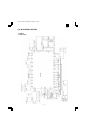
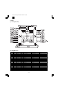
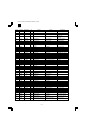
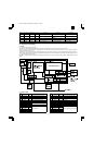
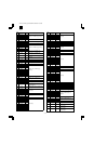
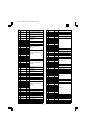
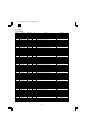

(4) I/O ASIC
a. pin/signal table
Pin No. Pin name Signal name I/O Purpose Descriptions
1 GND POW
2 GND POW
3 SCK IN 0: Level fixing input
4 AMC IN 0: Level fixing input
5 SMC IN 0: Level fixing input
6 UART0SIN/SIN OPECMD IN Operation panel command interface
7 UART0SOUT/SOT OPESTS OUT Operation panel command interface
8 UART0CTSB /OPESRDY IN Operation panel command interface
9 UART0RTSB /OPECRDY OUT Operation panel command interface
10 GND POW
11 UART1SIN OPECMD IN Electronic sort option command interface
12 UART1SOUT OPESTS OUT Electronic sort option command interface
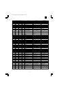
13 UART1CTSB /OPESRDY IN Electronic sort option command interface
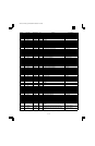
14 UART1RTSB /OPECRDY OUT Electronic sort option command interface
15 UART2SIN OPECMD IN FAX option command interface
16 VCC POW
17 UART2SOUT OPESTS OUT FAX option command interface
18 UART2CTSB /OPESRDY IN FAX option command interface
19 UART2RTSB /OPECRDY OUT FAX option command interface
20 GND POW
21 VCC POW
22 GND POW
23 UART3SIN OPECMD IN PQL option command interface
24 UART3SOUT OPESTS OUT PQL option command interface
25 UART3CTSB /OPESRDY IN PQL option command interface
26 UART3RTSB /OPECRDY OUT PQL option command interface
27 VCC POW
28 DSLED1 LED1 OUT 3; Beam document size sensor control
29 DSLED2 LED2 OUT 3; Beam document size sensor control
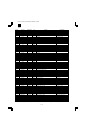
30 DSLED3 LED3 OUT 3; Beam document size sensor control
31 DSIN0 DSIN1 IN 1: Beam document size sensor detection
32 GND POW
33 DSIN1 DSIN2A IN 2: Beam document size sensor A detection
34 DSIN2 DSIN2B IN 2: Beam document size sensor B detection
35 DSIN3 DS3IN IN 3: Beam document size sensor detection
36 PMC0POUT0 MIRMODA OUT Mirror motor phase A drive H: Drive
37 VCC POW
38 PMC0POUT1 MIRMODB OUT Mirror motor phase B drive H: Drive
39 PMC0POUT2 /MIRMODA OUT Mirror motor phase /A drive H: Drive
40 VCC POW
41 GND POW
42 GND POW
43 PMC0POUT3 /MIRMODB OUT Mirror motor phase /B drive H: Drive
44 PMC2POUT0 SFTDA OUT Shifter motor phase A drive H: Drive
45 PMC2POUT1 SFTDB OUT Shifter motor phase B drive H: Drive
46 PMC2POUT2 /SFTDA OUT Shifter motor phase /A drive H: Drive
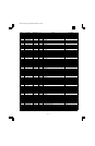
47 VCC POW
48 PMC2POUT3 /SFTDB OUT Shifter motor phase /B drive H: Drive
49 PMC3POUT0 LFTDA OUT Separator motor phase A drive H: Drive
50 PMC3POUT1 LFTDB OUT Separator motor phase B drive H: Drive
51 PMC3POUT2 /LFTDA OUT Separator motor phase /A drive H: Drive
52 GND POW
53 PMC3POUT3 /LFTDB OUT Separator motor phase /B drive H: Drive
54 PMC4POUT0 DPXDA OUT Duplex motor phase A drive H: Drive
55 PMC4POUT1 DPXDB OUT Duplex motor phase B drive H: Drive
56 PMC4POUT2 /DPXDA OUT Duplex motor phase /A drive H: Drive
57 TESTB IN 1: Level fixing input
58 TESTB IN 1: Level fixing input
59 GND POW
(Pin descriptions) IN: Input pin OUT: Output pin BIDIR: Bi-directional pin ODN: Open drain output pin TR1: 3-state output pin POW: Power pin
AR-161
AR-160/161 FM/E [13] ELECTRICAL SECTION 12/1/1998
13 – 8