


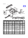
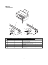
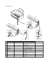
No.
Parts
Note
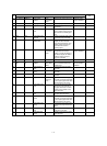
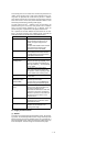
Code Signal name Name Type Function/operation Active condition
1 SYNC SYNC IN Laser beam sensor Bin diode Detects the laser beam position.
By this signal the left image print
start position is controlled.
LOW (0V) when
laser beam is
detected.
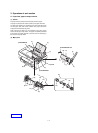
2 No. 1 mirror
3 No. 3 mirror Leads the laser beam to the OPC
drum.
4 Second cylindrical
lens
Corrects the laser beam
deflection by variations in the
scanning mirror angle. Corrects
the optical section dirt.
5Fθ mirror (No. 2
mirror)
Corrects the laser beam form and
pitch.
6 Scanning mirror
(rotation mirror)
Scans the laser beam and
performs imaging.
7 No. 1 cylindrical
lens
Adjust the direction of laser beam.
8 Laser diode Generates laser beam. (Controls
ON/OFF for imaging)
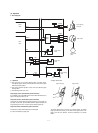
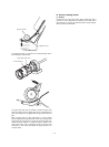
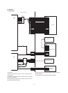
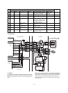
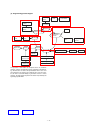
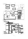
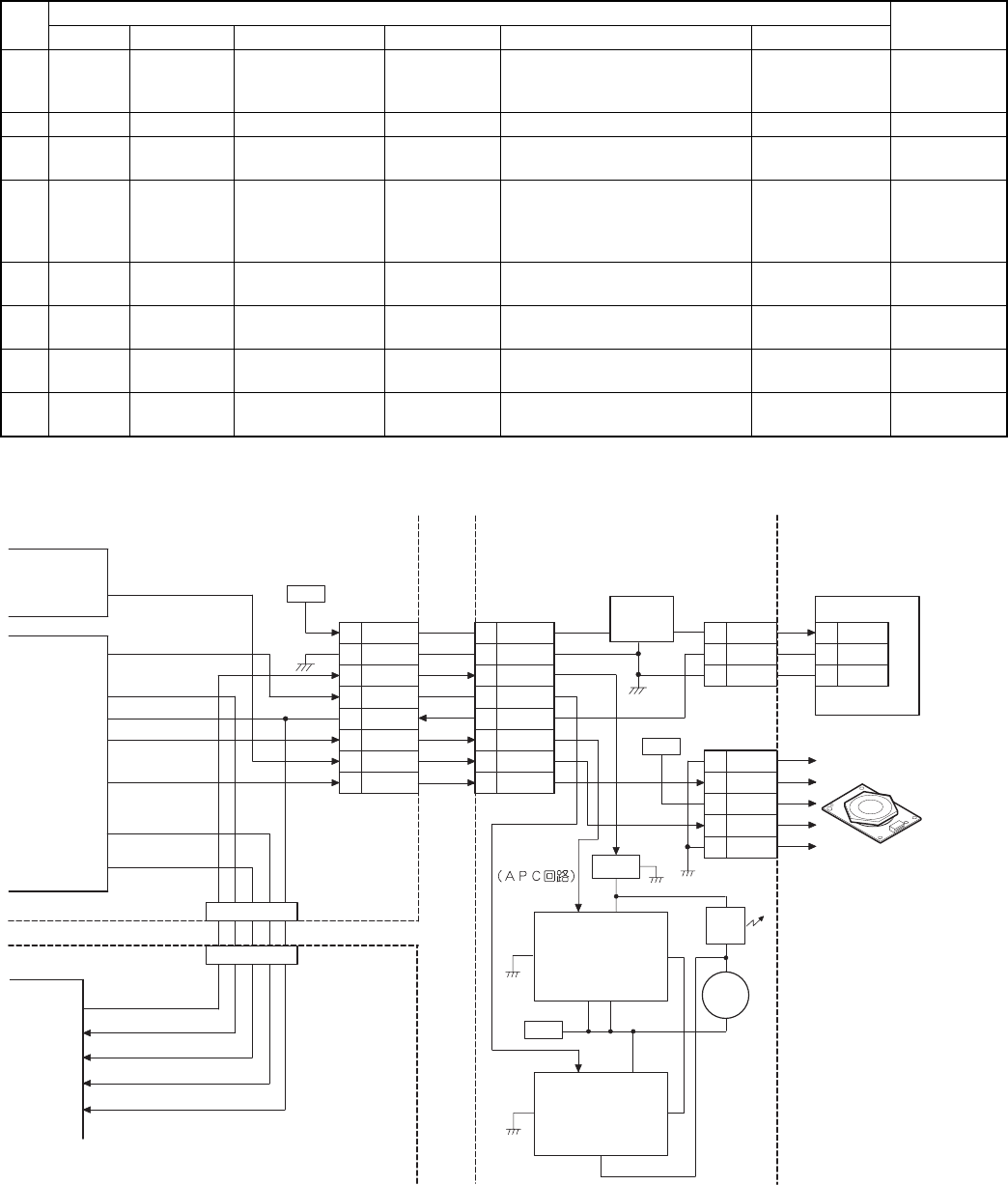
(4) Operation
a. Wiring diagram
SYNC-
+24V
1
CN9
GND
2
VDATA
3
SAMP
4
5
APCSTT
6
PMCLK
7
PMD-
8
+24V
APCSTT
PMD-
PRSTT
CN604
+5VL
1
2
GND3
31
CN603
+24V
3
1
2
CN602
PMCLK
4
5 GND
PMD-
+24V
LSU PWB
Q603
INH
OUT
VCC
VPS
GND
IM
IC601
LD
/PD
VR601
+5VL
IC603
2
1
5
3
78
4
SYNC_
VSYNC
PMCLK
+24V
CONT
VDD
GND
O/I
IC603
54
2
3
I/O
1
CPU
(IC5)
(IC8)
ASIC
LEND-
SAMP
(IC202)
ASIC
SDATA
LEND
PRSTT
VSYNC
SYNC
CN8
CN203
SYNC-
MCU(PCU) PWB
+24V
1
CN601
GND
2
VDATA
3
SAMP
4
5
APCSTT
6
PMCLK
7
PMD-
8
SYNC-
+5VL
1
2
GND3
SYNC_
ICU PWB
Laser beam detection PWB
(start position detection PWB)
3-termina
regulator
Scanning motor
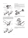
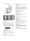
b. Operation
The APC circuit is started by the APCSTT signal sent from the MCU
(PCU) PWB, and laser diode is turned on/off according to the VIDEO
signal. (The laser diode is turned on when the VDATA signal is
HIGH.)
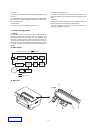
When the laser diode is turned on, 780nm infrared semiconductor
laser beams are radiated from the laser diode and arranged to be
parallel beams by the collimeter lens and focused to the photocon-
ductor drum by No. 1 cylinder lens and sent to the scanning mirror.
Rotation of the scanning mirror is controlled by the scanning motor to
scan laser beams.
1 – 13