


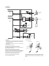
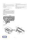
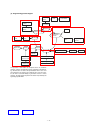
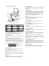

The scanning mirror is a 6-surface mirror. Six lines are printed for one
rotation of the scanning motor. Laser beams reflected by the scan-
ning mirror are passed to the curved mirror by the No. 1 reflection
mirror. Before reaching the curved mirror, the laser beams enter the
laser beam sensor on the start position detection PWB to make
horizontal synchronization (generating SYNC signal).
The laser beams from No. 1 reflection mirror are arranged to be
parallel beams by the curved mirror and passed to No. 3 reflection
mirror. The laser beams reflected by No. 3 reflection mirror are
passed through No. 2 cylinder lens to the photoconductor drum.
No. 2 cylinder lens corrects deflection of laser beams due to varia-
tions in the duplex scanning mirror installing angle, and leads the
stable laser beams for each line to the photoconductor drum.
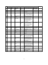
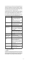
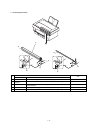
Part name Function
Laser diode The laser power is controlled by the
APC (Auto Power Control) circuit. In
addition, the paper empty sensor is
provided.
The laser diode radiates 780nm infrared
semiconductor laser beams under
control of the laser control PWB.
Collimator lens The collimator lens arranges laser
beams radiated from the laser diode to
be parallel beams and converges them
on the photoconductor drum.
No. 1 cylindrical lens Adjusts the direction of the laser beams.
Scanning motor/
Scanning mirror
Used to rotate the scanning mirror.
Started by the drive signal (PMD_) from
the PCU. The RPM is controlled by the
clock signal (PMCLK_). The motor RPM
is 11811 RPM.
The scanning mirror is a6-surface
mirror, and it reflects laser beams. By
this operation, 6 lines of printing is made
for one rotation of the scanning motor.
No. 1 mirror This mirror reflects laser beams to the
curved mirror.
Laser beam sensor
PWB (Start position
detection PWB)
Used to detect laser beams to make
horizontal synchronization.
The photo sensor on the PWB detects
laser beams to generate SYNC signal.
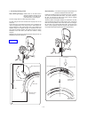
No. 2 mirror (Curved
mirror)
Laser beams are scanned by the
scanning mirror. But the dot interval of
laser beams radiated onto the
photoconductor differs at the center and
at the corners. This mirror corrects this
difference to provide even dot interval of
laser beams. For this reason, it is of
curved structure.
No. 3 mirror This mirror passes the laser beams
reflected from the curved mirror to the
photoconductor mirror.
No. 2 cylindrical lens This lens is used to correct laser beam
deflection due to variations in the
scanning mirror angle.
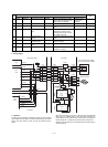
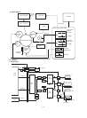
D. Image process section
(1) Outline
This section is composed of the photoconductor section, the develop-
ing section, the transfer/separation section. Images formed by laser
beams formed by the scanner (Writing) section are converted into a
latent electrostatic images, which are formed into visible images by
toner development. The toner images are transferred onto paper.
1 – 14