


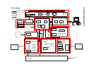
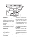
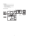
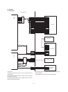
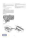
Scanner (read) section
In this section, the copy lamp (cathode ray tube, Xenon lamp)
radiates light onto a document, and the reflected light is detected by
the image sensor (CCD element) to convert into electrical signals
(analog signals), which are sent to the MCU PWB.
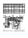
MCU (ICU) PWB
The image data from the scanner (reading) section are converted into
digital signals and subject to image process (correction, etc.), and
converted into dot image data and outputted to the scanner (writing)
section.
During printing, the dot image data from the ICU PWB are outputted
to the scanner (writing) section directly. The engine status data are
outputted to the ICU PWB.
The loads (motor, solenoid, etc.) are controlled according to the sen-
sor/detector signal.
The above operation is performed by the CPU, ASIC, and memory.
ICU PWB
Print data (compressed data) sent from the host are developed and
converted into dot image data and outputted to the scanner (writing)
section. The engine status data sent from the MCU (PCU) PWB are
outputted to the host (PC).
Scanner (writing) section
In this section, the dot image data sent from the MCU PWB are
converted into laser beams (ON/OFF), which is scanned to form
latent electrostatic images on the OPC drum.
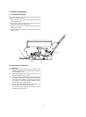
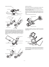
Paper feed section
The paper feed roller feeds paper to the transfer section.
The paper feed operation is controlled by the paper fed roller clutch
and the paper feed roller clutch solenoid.
Image process
This section is composed of the photoconductor section, the develop-
ing section, and the transfer/separation section. The images formed
by laser beams in the scanner (writing) section are formed into latent
electrostatic images on the photoconductor and converted into visible
images by toner development.
The operations of this section are composed of five processes; ex-
posure, development, transfer, separation, and discharge.
The OPC drum is used as the photoconductor drum, and one-com-
ponent toner is employed.
For charging, the rotation brush is employed. For transfer, the roller is
employed to eliminate ozone generation. In addition, t is compact.
The high voltage required in this section is supplied by the high
voltage PWB.
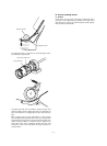
Fusing/paper exit section
Toner is fused to the paper in the fusing/paper exit section using heat
and pressure.
The heat roller surface temperature is detected by the fusing
temperature sensor to maintain the constant fusing temperature (155
˚C).
The heater lamp is driven by the power PWB unit.
Operation PWB
The operation PWB displays various information and supplied the key
operation signals to the MCU (PCU) PWB.
High voltage power PWB
The high voltage power PWB outputs the high voltage for the main
charger, the developing bias, and the transfer charger. In addition,
the main motor drive circuit is built into the PWB.
Main motor.
The main motor drives the paper feed section, the transport section,
the image process section, and the fusing section.
The main motor drive circuit is built into the high voltage power PWB.
Copy lamp control PWB
The copy lamp light quantity is controlled to provide necessary light
quantity even though the conditions of the scanner (reading) section
are changed.
The copy lamp drive voltage is controlled by the output level of the
light quantity sensor in the scanner (reading) section.
Power PWB
The power PWB outputs the DC power voltages (+24V, +5V, +3.3V,
+12V), and drives the heater lamp.
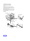
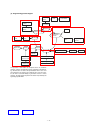
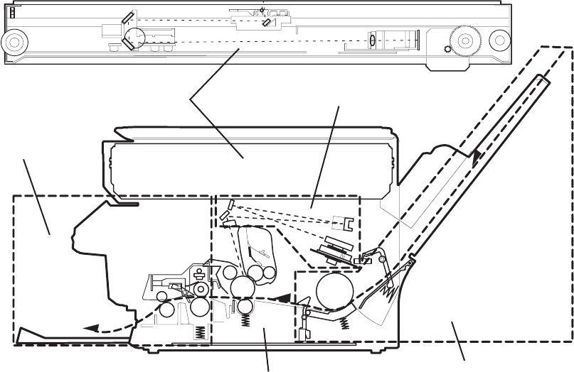
Scanner (reading) section
Fusing/paper exit section
Scanner (writing) section
Paper feed section
Image process section
1 – 2