


UX-2200CMU/CMC
FO-2150CMU/CMC
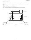
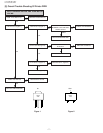
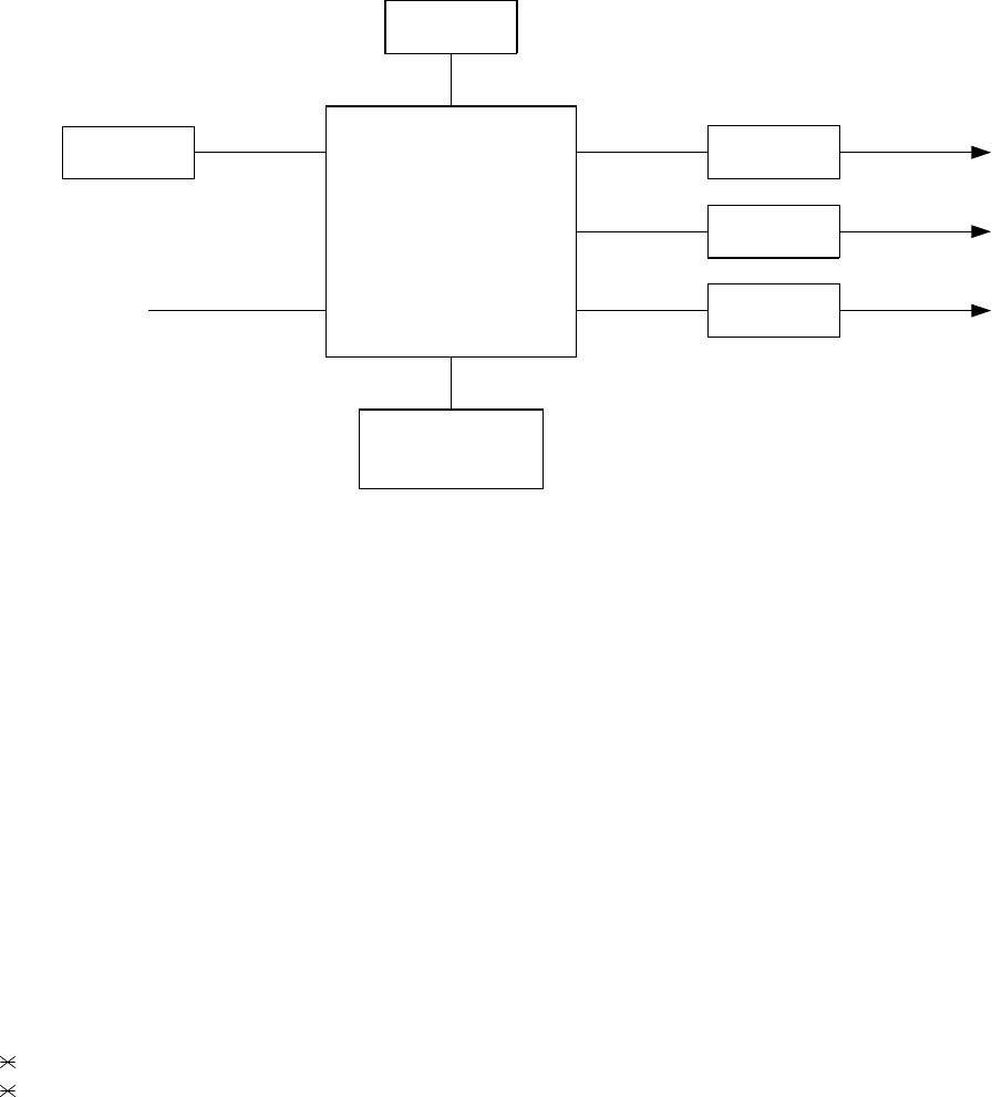
3. Electricai Overview
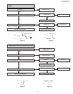
The information in this section appears in a sequence relative to the system diagram in the following figure.
4. Power Supply Connector
The mechanism requires two voltages (+5V and +24V).
These two voltages supplied from CNPRT connector.
5. Host interface connector
Connector CNPRT on the printer PWB provides 28 lines from the host unit, for control of various operating options
available to the host.
The two primary functions of the host interface are:
Printing data for the Ink Jet Printer.
Error status to the host.
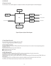
6. ASIC, RAM, and CPU
The Application Specific Integrated Circuit(ASIC) combines several blocks of circuitry into one chip.
Descriptions of circuitry within the ASIC appear later in the section.
A microprocessor bus, which extends inside the ASIC, carries data among the CPU(include internal ROM), RAM, and
ASIC circuitry.
The ROM (inside CPU) is a 8K Byte chip that contains the software code (firmware) for the Ink Jet Printer.
The RAM is a 32 K Byte chip that stores print data and other variable information.
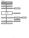
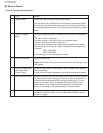
Figure 2 System of printer Block diagram
Driver
Driver
SRAM
Sensor
•Home Position
•Paper-IN
8bit
MPU
Host Interface
TO FAX PWB
ASIC
Head
Carriage Motor
Feed Motor
Driver
– 3 –