


10
E
n
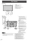
Front view
768
11
33
2
3
5
4
2
1. Sensor
2. Touch pen ultrasonic sensor
3. Reective surface
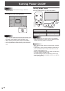
4. Power button (Seepage16.)
5. Tray
6. Remote control sensor (Seepage15.)
7. Input switch (Seepage21.)
8. Power LED (Seepage16.)
Part Names
n
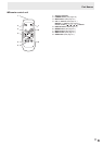
Rear view
18
17
16
19
22
21
20
24
23
2
1
4
1514
5
6
7
8
9
10
11
12
3
25
13
When the PN-ZB01
(optional) is attached
1. Optional attachment section
This section is used to connect optional
hardware for function expansion.
Offering this attachment location is
not a guarantee that future compatible
hardware attachments will be released.
2. Speakers
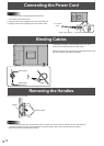
3. Handles (Seepage14.)
4. Vents
5. Expansion terminal cover
Additional input/output terminals are
availablebyattachingthePN-ZB01
expansion board (optional).
6. PC/AV HDMI input terminal (See page
12.)
7. PC D-sub input terminal (See page
12.)
8. Audio input terminal (Seepage12.)
9. Audio output terminals (Seepage12.)
10. RS-232C output terminal (See page
12.)
11. RS-232C input terminal (Seepage12.)
12. Optional terminal
This terminal is provided for possible
future (optional) function expansion.
Offering of this terminal is not a
guarantee that future expanded
functionality will be provided.
13. USB port
14. AC input terminal (Seepage14.)
15. Main power switch (Seepage16.)
Caution
• ConsultyourSHARPdealerforattachment/detachmentof
optional parts.
• Donotopentheexpansionterminalcoverbyyourself.
There are high voltage parts inside the cover which may
cause an electric shock.
When the PN-ZB01 (optional) is attached
16. PC/AV DVI-D input terminal (Seepage13.)
17. PC/AV DVI-D output terminal (Seepage13.)
18. LAN terminal (Seepage13.)
19. External speaker terminals (Seepage13.)
20. Audio 1 input terminals (Seepage13.)
21. Audio 2 input terminals (Seepage13.)
22. PC RGB input terminals (Seepage13.)
23. AV component input terminals (Seepage13.)
24. AV video input terminal (Seepage13.)
25. AV S-video input terminal (Seepage13.)