


25
4
Appendix
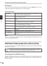
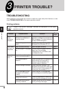
PARALLEL INTERFACE
This printer uses a bi-directional parallel interface. Use the interface cable attached to the AL-
840.
●
Use the parallel interface cable specified by SHARP for prevention of external
radio wave interference. For details, contact your SHARP service centre.
●
For specifications of the parallel interface of your computer, see its operation
manual.
Connector
36-pin DDK 57LE-40360-730B (D29)
female connector or equivalent connector
Cable
Shielded type bi-directional parallel
interface
For best results, use a printer interface
cable which is IEEE 1284 compliant.
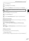
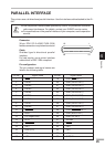
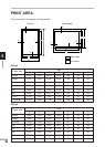
Pin configuration
The pin numbers and signal names are
listed in the following table.
1
18
36 19
Pin No. Signal name Pin No. Signal name
1 STB 19 GND (STB RET)
2 DATA1 20 GND (DATA1 RET)
3 DATA2 21 GND (DATA2 RET)
4 DATA3 22 GND (DATA3 RET)
5 DATA4 23 GND (DATA4 RET)
6 DATA5 24 GND (DATA5 RET)
7 DATA6 25 GND (DATA6 RET)
8 DATA7 26 GND (DATA7 RET)
9 DATA8 27 GND (DATA8 RET)
10 ACKNLG 28 GND (ACKNLG RET)
11 BUSY 29 GND (BUSY RET)
12 PE (Paper End) 30 GND (PE RET)
13 SLTC 31 INPRM
14 AUTO LF 32 FAULT
15 (NC) 33 (NC)
16 GND (0 V) 34 (NC)
17 FG 35 +5V
18 +5V 36 SLTC IN