


Installation and Maintenance Manual
Solid State Auto-Switch Series D-P5DW
This manual should be read in conjunction with the current product catalogue
For future reference, please keep this manual in a safe place
Safety Instructions
These safety instructions are intended to prevent a hazardous situa-
tion and/or equipment damage.These instructions indicate the level
of potential hazard by label of “Caution”,“Warning”or “Danger”.
To ensure safety,be sure to observe ISO4414
(Note1)
, JIS B 8370
(Note2)
and other safety practices.
Note 1:ISO 4414: Pneumatic fluid power – Recommendations for the
application of equipment to transmission and control systems.
Note 2: JIS B 8370: Pneumatic system axiom.
CAUTION : Operator error could result in injury or
equipment damage.
WARNING : Operator error could result in serious
injury or loss of life.
DANGER : In extreme conditions, there is a
possible result of serious injury or loss of life.
WARNING
1. The compatibility of pneumatic equipment is the respon-
sibility of the person who designs the pneumatic system
or decides its specifications.
Since the products specified here are used in various operating
conditions, their compatibility for the specific pneumatic system
must be based on specifications or after analysis and/or tests to
meet your specific requirements.
2. Only trained personnel should operate pneumatically
operated machinery and equipment.
Compressed air can be dangerous if an operator is unfamiliar
with it.Assembly, handling or repair of pneumatic systems should
be performed by trained and experienced operators.
3. Do not service machinery/equipment or attempt to
remove component until safety is confirmed.
1) Inspection and maintenance of machinery/equipment should
only be performed after confirmation of safe locked-out
control positions.
2) When equipment is to be removed,confirm the safety process
as mentioned above. Switch off air and electrical supplies and
exhaust all residual compressed air in the system.
3) Before machinery/equipment is re-started, ensure all safety
measures to prevent sudden movement of cylinders etc.
(Bleed air into the system gradually to create back-pressure,
i.e. incorporate a soft-start valve).
4. Contact SMC if the product is to be used in any of the
following conditions:
1) Conditions and environments beyond the given specifica-
tions, or if product is used outdoors.
2) Installations in conjunction with atomic energy, railway, air
navigation, vehicles,medical equipment, food and beverage,
recreation equipment, emergency stop circuits, press
applications, or safety equipment.
3) An application which has the possibility of having negative
effects on people, property, or animals, requiring special
safety analysis.
CAUTION
Ensure that the air supply system is filtered to 5 micron.
1. Product specification
Model number D-P5DW
Wiring style Two wire type, Non-polarity
Application 24V DC Relay, PLC
Source voltage ––
Current consumption ––
Load voltage DC24V (DC20~28V)
Load current 6~40mA
Internal voltage drop 5V or less
Leak current 1mA or less at DC24V
Operating time 40ms or less
Operating
Two colour
indicator lamp*1
Magnet field
AC16000A
proof *2
Proof impact 1000m/s
2
Insulation resistance 50M Ω or more at DC500V mega
Proof voltage AC1000V for 1 minute (lead wire, between cases)
Ambient temperature -10~60°C
Protection structure IEC529 standard IP67, JISC0920
*1 Operating position. ..Red diode lights,Optimum operating position .. .Green diode lights
*2 Applicable adjacent to conductor (0mm)
or Solenoid valve, a built-in surge protection circuit is installed.
If an auto-switch is to be used to generate an inter-lock signal,which
requires high reliability, then instigate mechanical protection,or place
another switch, double inter-lock style, together. Ensure the correct
operation of this Inter-lock frequently.
Ensure, when installing this product, that enough space is
available for maintenance to be carried out.
CAUTION
Do not subject this product to any form of impact damage.
Do not lift an actuator, fitted with an auto-switch,by the switch lead,
as stress may be applied to the inside of the switch.
Ensure auto-switch mounting screw is tightened to the correct torque
(see Mounting of switch bracket).
Adjust the auto-switch so that the ON position coincides with the cen-
tre of the operating area. If the switch is set to one side or the other
of this centre position then inconsistent operation will occur.
Wiring
Do not apply repeated bending or tensile forces to the
connecting wiring as this may cause disconnection. Bend radius is
approximately R40mm or more.
Connect the load before applying power to the switch,failure to do so
may cause excess current to damage the switch.
Ensure wiring is carried out correctly. Not all wiring modes have pro-
tection and the switch may be damaged.
Separate signal lines from power/high voltage lines to prevent 'noise'.
Ensure all wiring is correctly and fully insulated.
WARNING
DO NOT USE THIS SWITCH IN AN EXPLOSIVE ATMOSPHERE.
Do not use this switch in high magnetic fields, as this will damage the
switch and actuator magnet.
Do not use this switch in water-laden atmospheres, oil or chemical
laden atmospheres.
Do not use this switch in conditions where temperatures are outside
of the switch operating Spec.
Protect the switch from weld spatter and accumulation of iron dust etc.
Maintenance
To avoid incorrect operation periodic maintenance should be carried out.
• Check tightness of mounting screw regularly to prevent possible
movement of the switch from its set position.
• Regularly check condition of the wiring.Repair insulation damage
immediately or replace the switch.
• If a red LED is showing this indicates that the switch has moved
from the set position. Re-adjust the switch until the green LED is
showing (this is the optimum position).
CAUTION
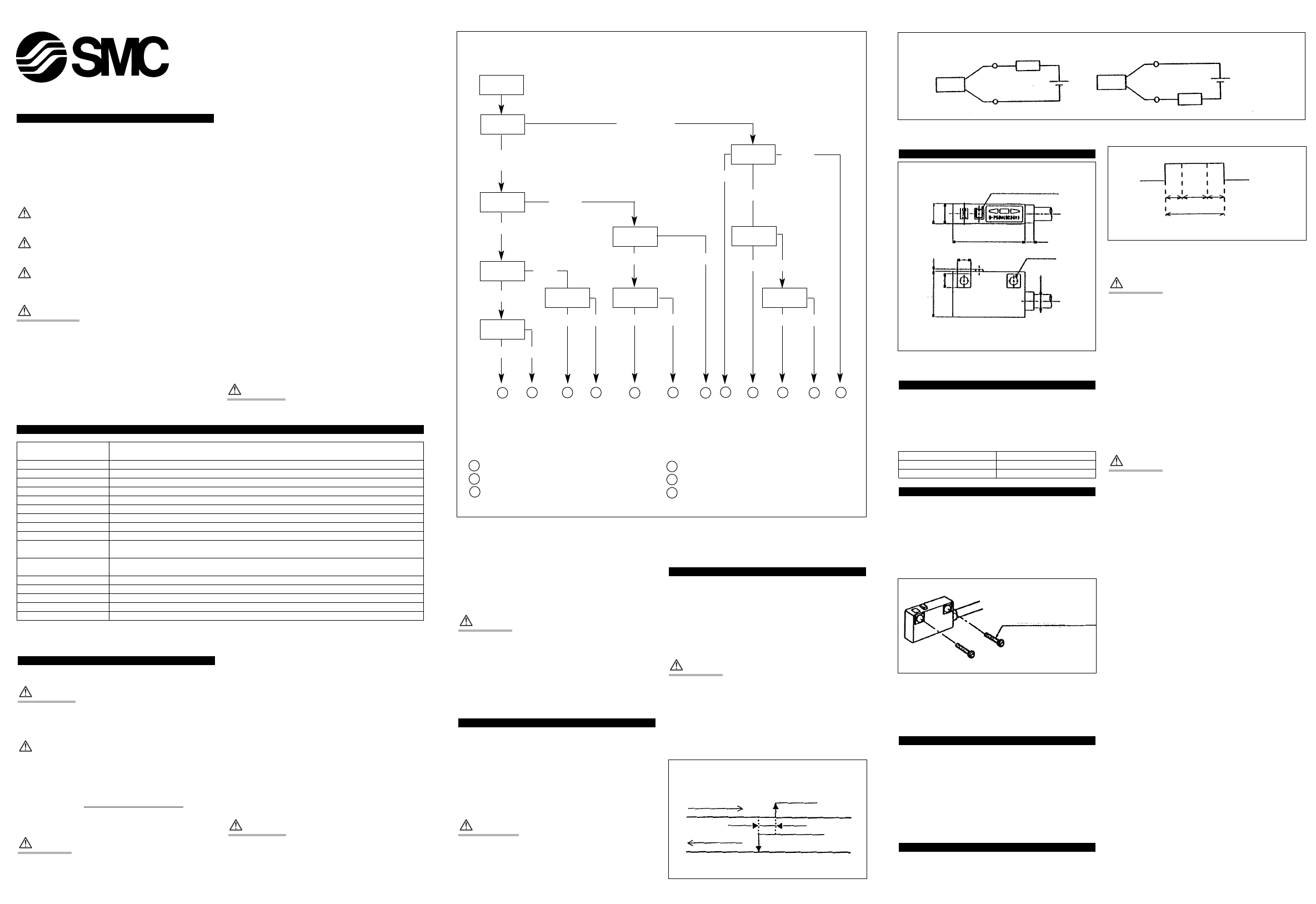
If detection failure occurs i.e. LED remains ON follow the faultfinding
chart above (Fig 1).
For applications involving contact with water, elasticity, and welding,
contact your nearest SMC Office. (See at the end of this Manual.)
If the hysteresis, between the ON and OFF position of the switch is
incorrect please consult SMC.
Exterior dimensions
Basic wiring (Fig 4)
Lead wire colour in brackets indicates products complying with IEC.
Connection with PLC (sequence controller)
Depending on the PLC input specification,the output design of 3 wire
type switches and 2 wire type switches differ. (See below)
PLC input specification 2 wire connecting type
Sink input Sink output mode
Source input Source output mode
Mounting of switch bracket
Each actuator has a specified mounting bracket to mount the switch
to the actuator.The type of bracket depends on the following:
• Type of actuator, and tube O.D. Please consult the current
actuator catalogue for details.
When fitting an auto-switch for the first time please ensure that the
actuator is fitted with a magnet and that the brackets are correct for
the actuator type.
Appropriate tightening torque
M3 mounting screw correct tightening torque is 0.5~0.7 Nm (5.1~7.1
kgf.cm)S
Setting the switch detection position (Fig 6)
Position the actuator at its stroke end.
Single colour display
Move the auto-switch into the centre of the operating range and
ensure that the red LED is ON.
Two colour display
Move the Auto-switch into the centre of the operating range and
ensure that the green LED is ON.
Detecting actuator stroke end
Refer to dimensions A & B in the actuator catalogue.
CAUTION
Welding current
This product has no immunity against high magnetic fields.Do not use
in applications where welding takes place using D.C.inverter/rectified
source. If using in conjunction with a D.C. welding application remove
the switch from the D.C. source and operate it as a standard switch.
As a rule of thumb, in this type of application,to prevent malfunction
use the scale 10,000A switch which should be at least 30cm away
from the source.
Effect of magnetisation/de-magnetisation
In the case of exceeding the 10,000A, although this is very rare, the
detecting performance of the switch will deteriorate, due to
de-magnetisation (the magnetic field shrinks) of the detecting
magnet. Parts around the actuator also become magnetised.
Should any malfunction occur please contact your nearest SMC office
for advice.
CAUTION
In all cases do not clean with a solvent solution.
013A/ENGD-#S-TFI99GB
When you enquire about the product, please contact the following
SMC Corporation:
ENGLAND Phone 01908-563888 TURKEY Phone 212-2211512
ITALY Phone 02-92711 GERMANY Phone 6103-402-0
HOLLAND Phone 020-5318888 FRANCE Phone 01-64-76-10-00
SWITZERLAND
Phone 052-396 31 31 SWEDEN Phone 08-603 07 00
SPAIN Phone 945-184100 AUSTRIA Phone 02262-62-280
Phone 902-255255 IRELAND Phone 01-4501822
GREECE Phone 01-3426076 DENMARK Phone 70 25 29 00
FINLAND Phone 09-68 10 21 NORWAY Phone 67-12 90 20
BELGIUM Phone 03-3551464 POLAND Phone 48-22-6131847
PORTUGAL Phone 02-610 8922
Installation
Actuators
WARNING
To eliminate the possibility of magnetic interference between switch-
es, please ensure that, when two or more actuators are used, in
parallel,they are kept at least 40mm apart.
Mid-stoke position sensing
Exercise caution when attempting to detect the piston at mid-position,
without stopping, as the switch detection time may be too short,
particularly at relatively high actuator speeds. Detectable max. piston
speed can be obtained by the following formula:
V (mm/s) =
Auto switch operating range (mm)
Load operating time (ms)
x1000
Where possible keep all wiring as short as possible.
CAUTION
If the 2-wire type solid state auto-switch has a large internal voltage
drop, and leakage current is also high,it is possible that the load may
not operate correctly due to incorrect load spec.Please confirm the fol-
lowing conditions before operation,and note that the internal voltage
drop and leak current have a considerable influence on the serial and
parallel connection of the 2-wire solid state switch.
Leak current influence
I.E Voltage generated to the load when the power is turned off.
Voltage generated = Auto-switch leak current x load resistance. If this
voltage exceeds the OFF voltage of the load,it is possible that the load
may stay ON. In order to match the condition of the controller-input
unit and leak current,then auto-switch leak current must be less than
input unit OFF current.
Internal voltage drop
Should an internal voltage drop occur, then the load supply voltage
will also drop as the switch operates. (Load supply voltage = Source
voltage – Internal voltage drop).
When the load supply voltage becomes lower than the switch ON
voltage, the load may not operate correctly.
WARNING
Incorrect load voltage
Although the switch will operate correctly, even if the load current is
below the limit of the specification, the indicator light will be
'dimmed'.If the load current falls to 3mA, or lower,the operation may
not start.
Ensure that,if using a load that can generate a surge voltage ie. Relay
Fig 1
Fig 2
Fig 3
Fig 4
Load spec. check ᕡ . . .ON voltage > Load voltage - Internal voltage drop
Load spec. check ᕢ . . .OFF current > Leak current
. . .Switch output parts failure (replace)
. . .Correct wiring
. . .Replace switch 2 wires Ǟ 3 wires
. . . .Switch failure
. . . .Replace cylinder. Detectable magnet field inadequate (No magnet)
. . . .Replace PLC input board or replace switch 2 wire Ǟ3 wires
Fig 5
Fig 6
D-5DW
Autoswitch set screw
M3x0.5x10l
Problem
Condition
Indicator
lamp lights
2 wires/
3 wires
Source voltage
or load voltage
Stay OFF
(sometimes ON)
Normal
3 wires
Normal
Normal
Normal
Normal
Abnormal
Abnormal
Abnormal
Abnormal
Stay OFF
Stay OFF
Indicator
lamp lights
Load spec.
check ᕡ
Load spec.
check ᕢ
Replace the
switch
2 wires/
3 wires
Stay ON
(sometimes OFF)
Normal
2 wires
Normal
Stay ON
Wiring
(output) check
A
A
A AAB
B
B
B
C
C
D
D
D
E
E
F
F
Piston moving
direction
Piston moving
direction
ON position
Hysteresis
Hysteresis
OFF position
Indicator lamp
4
2-ø3. 5
32
6
9. 2
8. 8
5
20
1
ø6
ø3. 4
ON
OFF
Red Red
Green
Operating range
2 wire type (Sink output)
2 wire type (Source output)
Switch
Load
Brown (Red)
OUT(-)
OUT(+)
Power
source
Switch
Load
Brown (Red)
OUT(-)
OUT(+)
Power
source
Blue (Black)
Blue (Black)
3 wires
2 wires
Abnormal