


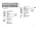

– 17 –
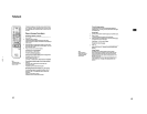
KP-41S5/41S5B/41S5G/
41S5K/41S5R/41S5U
RM-862
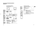
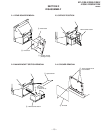
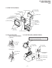
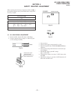
2-7. BEZNET SECTION REMOVAL
1 Screws
(+ BVTP 4X16)
2 Seven screws
(+ BVTP 4X16)
3 Four screws
(+ BVTP 4X16)
5 Four screws
(+ BVTP 4X12)
4 Beznet assembly
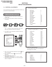
8 Screen holder (H)
9 Screen holder (V)
0 Screen holder (H)
!¡ Screen holder (V)
!™ Duffusion plate (F)
!£ Duffusion plate (L)
!¢ Contrast screen
6 Four screws
(+ BVTP 4X12)
7 Eight screws
(+ BVTP 4X12)
!∞ Mirror cover
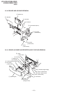
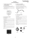
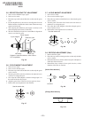
2-9. SLANT MECHASEAL ASSEMBLY REMOVAL
1 Rubber cap
2 HV cable
turn 90°
2 Rubber cap
1 HV cable
Hook
Gutter
(1) Removal
(2) Installation
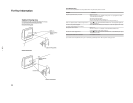
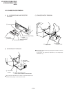
2-8. HIGH-VOLTAGE CABLE
INSTALLATION AND REMOVAL
1 Four screws
(+ BVTP 4X16)
5 Four screws
(+ BVTP 4X16)
2 CR board
3 Neck assembly
4 Deflection yoke
6 Slant mechaseal
assembly (R)
7 Extension spring
Removing the arrow-marked screw is strictly inhibited.
If removed, it may cause liquid spill