


Miscellaneous
Specifications
59
SYNC: 1 Vp-p, 75 ohm terminated,
sync negative
S VIDEO (Separate luminance (Y) and
chrominance (C) signals):
4-pin mini-DIN × 1
Y: 1 Vp-p, 75 ohm terminated, sync
negative
C: For NTSC/EIA standards: 0.29
Vp-p color burst, 75 ohm terminated
For PAL B.G.I. standards:
0.3 Vp-p color burst, 75 ohm
terminated
VIDEO (NTSC composite video signal
for NTSC/EIA standards and PAL
composite video signal for PAL
B.G.I. standards) BNC connector ×1
1 Vp-p, 75 ohm terminated, sync
negative
Controls connectors
REMOTE 1: special mini jack ×1
For RM-5500 Remote Control Unit
(not supplied)
REMOTE 2 (automatic printing
connector): Stereo mini jack: × 1
For RM-91 Remote Control Unit
(See “Assigning Functions to the
Remote Control Unit” on page 52.)
RS-232C (Computer control
interface):
D-SUB 25-pin connector ×1
Output: 5-kilohm load
Typical ± 8 V
Input: 5-kilohm load
High level 5 to 15 V
Low level –5 to –15 V
Supplied accessories
Color printing pack (1)
Paper tray (1)
AC power cord (1)
Warranty card (1) (for the customers in
the U.S.A. and Canada only)
CD-ROM (for the customers in the
Europe only)
Thermal head cleaning cartridge (1)
Instructions For Use (1)
Optional accessories
UPC-21L Color Printing Pack
UPC-21S Color Printing Pack
Medical Specifications
Protection against electric shock:
Class I
Protection against harmful ingress of
water:
Ordinary
Degree of safety in the presence of
flammable anesthetics or oxygen:
Not suitable for use in the presence
of flammable anesthetics or oxygen
Mode of operation:
Continuous
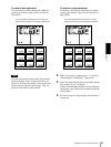
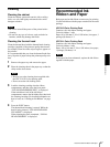
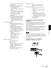
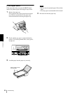
Using the automatic printing capabilities
(REMOTE 2)
If you send remote control pulse signals as illustrated
through the REMOTE 2 connector, the printer can be
remotely controlled according to the remote control
setting. (See page 52.)
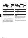
Turn on the power of the printer and display the source
image on the monitor screen. Send a remote control
pulse signal at the timing shown below.
The timing depends on the setting on item IMMED.
CAP of the FUNCTION SETUP menu.
Note
The remote control pulse signal examples introduced
here are one example of typical operation timing. The
timing may be affected due to the memory page selected
and print type.
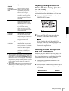
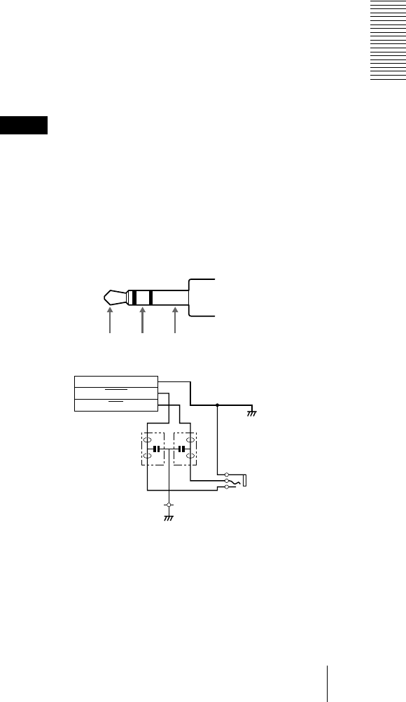
CAPTURE timing pulse for REMOTE 2:
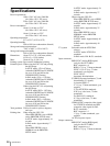
REMOTE 2 connector pin assignment:
GND
BUSY
MIN
FL2 FL1
2
5
CN5
3
MIN BUSY GND