


138
Others
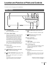
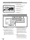
Location and Function of Parts and Controls (Continued)
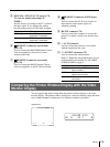
qh R/G/B/D/L button (86)
Press this button to display or clear the
COLOR ADJUST menu on the regular
screen.
qj LOAD COLOR button (87)
Press this button to recall the values set for the
printout color (color intensity and color
contrast). Pressing this button causes the
currently selected LOAD COLOR number to
be displayed for about three seconds. Three
kinds of LOAD COLOR numbers are
available for the currently selected user set. To
select the desired LOAD COLOR number,
release the button while the desired LOAD
COLOR number is displayed.
The selected LOAD COLOR number in the
COLOR ADJUST menu changes linked with
this button.
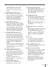
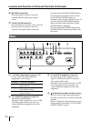
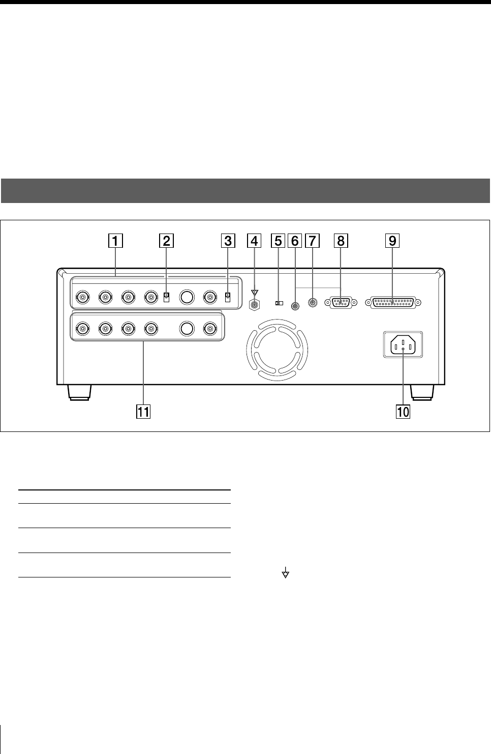
Rear
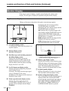
1 t INPUT (input signal) connectors (74)
Used to connect the video equipment
supplying the source image.
Connectable equipment
Video equipment with Y/C separated
output connector
Video equipment with composite video
signal output connector
Video equipment with RGB/SYNC
output connectors
Connector
S-VIDEO
VIDEO
RGB SYNC
2 75 Ω ON/OFF termination switch (74)
Provided for the RGB input.
Normally set this switch to ON. Set it to OFF
if the input signal should drop when you
connect additional equipment to the video
equipment.
3 75 Ω ON/OFF termination switch (74)
Provided for the NTSC composite video
signal in NTSC mode and PAL composite
video signal in PAL mode.
Normally set this switch to ON. Set it to OFF
if the input signal should drop when you
connect additional equipment to the video
equipment.
4
Equipotential ground terminal connector
Used to connect to the equipotential plug to
bring the various parts of a system to the same
potential.
Refer to “Important safeguards/notices for use
in the medical environments” for UP-51MD/
51MDU/51MDP on page 2.