


139
Others
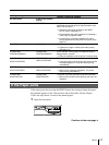
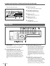
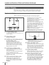
5 NTSC/PAL (NTSC/PAL TV) selector (74,
75) (only for models other than UP-
51MDU)
Set this selector according to the TV system of
the input signal. If you change this setting,
turn the printer power off, then back on again.
6
REMOTE 1 connector (special mini
jack) (76)
Used to connect the RM-5500 Remote Control
Unit (not supplied) to be used as a wired
remote control unit.
7
REMOTE 2 connector (stereo mini
jack) (76)
Used to connect the RM-91 Remote Control
Unit (not supplied), or the FS-36 Foot Switch.
8
REMOTE 3 connector (D-SUB 9-pin)
(76)
Used to connect the FS-30 Foot Switch. Or
input remote control pulse signals for
automatic printing.
9 RS-232C connector (76)
Used to connect the computer to control the
printer. For details, contact your nearest Sony
dealer.
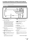
0 - AC IN connector
Used to connect the printer to a wall outlet
with the supplied power cord.
qa T OUTPUT connectors (75)
Used to connect the video monitor.
Refer to “Important safeguards/notices for use
in the medical environment” for UP-51MD/
51MDU/51MDP on page 2.
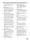
When
The NTSC system video
equipment is connected.
The PAL system video
equipment is connected.
Selector position
NTSC
PAL
Connector
S-VIDEO
VIDEO
RGB SYNC
COLOR : 200
Q1 A 4F:1
S
Q1 A 4F : 1 S
COLOR : 2 0 0
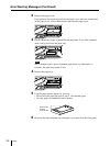
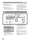
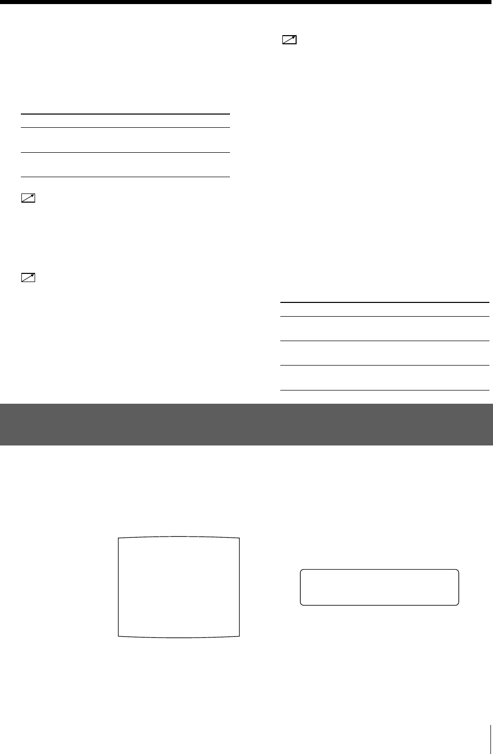
Regular screen
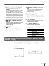
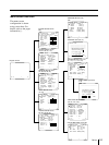
Comparing the Printer Window Display with the Video
Monitor Display
You can operate the printer using either the printer window display or the video
monitor display. The printer window display has a narrower display range and show
only a limited number of characters. Use whichever method you prefer.
Connectable equipment
Video monitor with Y/C separated
input connector.
Video monitor with composite video
signal input connector
Video monitor with RGB/SYNC input
connectors.