LZT 123 1836 28
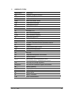
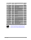
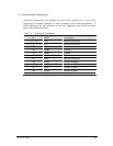
Pin Name Direction Function
PIN
Connection
Required
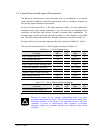
38 LED2 Output LED control
39 TX_ON Output Transmit indication
40 GPIO1 In/Out General purpose IO
41 GPIO2 In/Out General purpose IO
42 Reserved - -
43 GPIO3 In/Out General purpose IO
44 GPIO4 In/Out General purpose IO
45 GPIO5 In/Out General purpose IO
46 Reserved - -
47 Reserved - -
48 GPIO6 In/Out General purpose IO
49 GPIO7 In/Out General purpose IO
50 GPIO8 In/Out General purpose IO
51 GPIO9 In/Out General purpose IO
52 BUZZER Output Buzzer Output
53 RI Output Ring Indicator
54 DCD1 Output Data Carrier Detect (UART1)
55 DTR1 Input Data Terminal Ready (UART1)
56 DSR1 Output Data Set Ready (UART1)
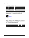
57 RTS1 Input Ready To Send (UART1) Yes
5
58 CTS1 Output Clear To Send (UART1) Yes
5
59 DTM1 Input Data To Module from host (UART1) Yes
4
60 DFM1 Output Data From Module to host (UART1) Yes
4
61 RTS2 Input Ready To Send (UART2)
62 CTS2 Output Clear To Send (UART2)
63 DTM2 Input Data To Module from host (UART2)
64 DFM2 Output Data From Module to host (UART2)
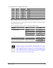
65 VREF Output Core voltage reference Yes
66 PCMCLK In/Out Serial PCM clock
67 PCMFS In/Out Serial PCM frame synchronization
68 PCMDTM Input Serial PCM data to module from host
69 PCMDFM Output Serial PCM data from module to host
70 SSPCLK In/Out SPI clock
71 SSPFS In/Out SPI frame synchronization
72 SSPDTM Input SPI data to module from host
73 SSPDFM Output SPI data to host from module
74 MMCCLK Output
SD/MMC card clock
75 MMCCMD In/Out
SD/MMC card command/response
76 MMCDAT0
In/Out SD/MMC card data 0


