LZT 123 1836 55
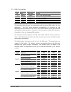
5.11.3 Control Signals (RTS1, CTS1, DTR1, DSR1, DCD1, RI)
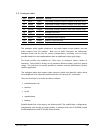
Depending upon the user application, some, all, or none of the control signals may
be needed. Each of the control signals can alternatively be configured as a general
purpose IO. When hardware flow control is not used in communications between the
application and the wireless modem, some applications may require RTS and CTS to
be connected to each other at the wireless modem. Users should familiarize
themselves with the specific implementation of their UART.
UART1 converted signals, together with GND, DTM1 and DFM1 form a 9-pin RS232
data port.
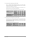
5.11.3.1 Hardware flow control RTS1 and CTS1
RTS and CTS provide a hardware flow control mechanism.
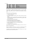
5.11.3.2 Request to Send (RTS1)
RTS is used to condition the DCE for data transmission. The default level is high by
internal pull up. The application must pull RTS low to enable data transmission from
the wireless modem. Similarly, the wireless modem asserts CTS low, indicating it is
ready to receive data transmission from the host.
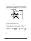
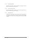
5.11.3.3 Clear To Send (CTS1)
CTS is asserted by the DCE to indicate that the host (DTE) may transmit data. When
CTS is high, the host (DTE) is not permitted to transmit data. The table below shows
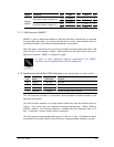
the load characteristics for this signal.
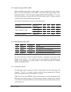
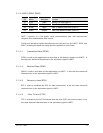
5.11.3.4 Data Terminal Ready (DTR1)
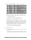
DTR indicates that the DTE is ready to receive data. It also acts as a hardware ‘hang-
up’, terminating calls when switched high. The signal is active low. Users can define
the exact behavior of DTR with an the AT&D command.


