SY-KT333 DRAGON Lite
Quick Start Guide
13
Installation
Connectors and Plug-ins
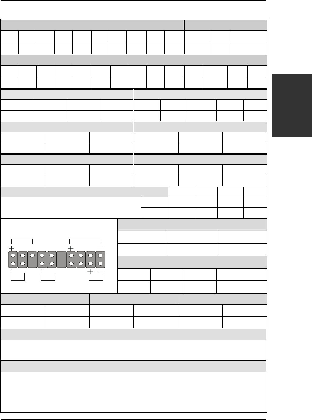
Standard IrDA (Infrared Device Header):SIRCON Wake-On-LAN Header: JP44
Pin1 Pin2 Pin3 Pin4 Pin5 Pin6 Pin7 Pin8 Pin9 Pin10
Pin1 Pin2 Pin3
VCC NC IRRX GND IRTX VCC NC CIRRX GND CIRTX
5V-SB GND MP_Wakeup
SMCARDCN
Pin1 Pin2 Pin3 Pin4 Pin5 Pin6 Pin7 Pin8 Pin9 Pin10 Pin11 Pin12 Pin13 Pin14
VCC NC NC NC Scrfet RST CLK NC NC Scrio GND Scrpres NC NC
USB3 USB4
Pin1 Pin2 Pin3 Pin4
Pin6 Pin7 Pin8 Pin9 Pin10
Power Data(-) Data(+) GND
Power Data(-) Data(+) GND GND
CPU Cooling Fan: CPUFAN1 CPU Cooling Fan: CPUFAN2
Pin1 Pin2 Pin3 Pin1 Pin2 Pin3
GND 12V SENSOR GND 12V NC
Chassis Fan: CHAFAN1 Chassis Fan: CHAFAN2/3
Pin1 Pin2 Pin3 Pin1 Pin2 Pin3
CONTROL 12V SENSOR GND 12V NC
CD -IN: CDIN1 / CDIN2 Pin1 Pin2 Pin3 Pin4
CDIN1 L G G R
Connect the CD Line-in cord from the CR-ROM
device to the matching connector CDIN
CDIN2 G L G R
Power LED
Pin1 Pin2 Pin3
VCC NC GND
Speaker
Pin1 Pin2 Pin3 Pin4
VCC NC NC Speaker out
HDD LED PWRBT RESET
Pin1 Pin2 Pin1 Pin2 Pin1 Pin2
LED Anode LED Cathode Power On/Off GND Control PIN GND
ATX Power On/Off: PWRBT
Connect your power switch to this header (momentary switch type).
To turn off the system, press this switch and hold down for longer than 4 seconds.
ATX Power Supply: ATX PW
Attach the ATX Power cable to this connector. (This motherboard requires an ATX power supply, an AT power supply can
NOT be used.)
When using the Power-On by PS/2 Keyboard function, please make sure the ATX power supply is able to provide at least
720mA on the 5V Standby lead (5VSB) in order to meet the standard ATX specifications.
Speaker
Reset
PWRBT
Power LED
HDD LED


