I/O Boards and Components 4-31
4
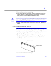
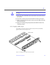
Caution – Graphics (UPA) cards have very fragile connectors. Press gently to
ensure pins do not break or bend.
Caution – Do not rock the card onto the socket; the plastic connector housing
may break.
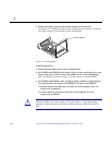
10. Press each corner of the card to ensure that it rests on the collar of the
standoff.
11. Press down on the tip insert of each standoff to lock the card in place.
12. Replace and tighten the back panel screws to secure the card to the
Graphics I/O board front panel.
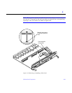
See Figure 4-15
13. Use the procedures in Section 4.5.3, “Installing a Board,” to replace the
Graphics I/O board.
4.5.6 Fibre Cards
4.5.6.1 Removing a Fibre Card
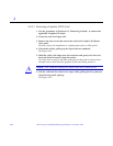
1. Use the procedures in Section 4.5.2, “Removing a Board,” to remove the
applicable I/O board.
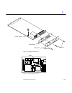
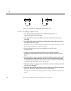
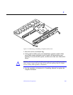
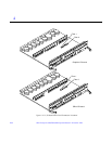
2. Locate the card to be removed. See Figure 4-23.
You may have to remove the SBus cards over (or next to) this card in order
to have enough room to hold onto the fibre card being removed. See
Figure 4-24.
!
!


