3-10 Sun StorEdge A3500/A3500FC Hardware Configuration Guide • December 1999
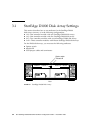
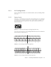
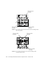
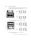
In this configuration (from the front of the expansion cabinet), the following occurs:
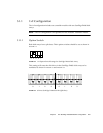
■ Controller module A controls disk arrays 1 and 2 in the 2x7 cabinet and disk
arrays 1 through 3 in the 1x8 cabinet (
FIGURE 3-19).
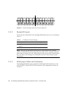
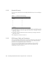
■ Controller module B controls disk arrays 3 through 7 in the 2x7 cabinet
(
FIGURE 3-20).
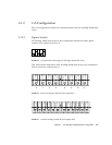
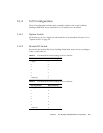
■ Controller module C controls disk arrays 4 through 8 in the 1x8 cabinet
(
FIGURE 3-21).
3.1.4.3 SCSI Jumper Cables and Terminators
All StorEdge D1000 disk arrays in this configuration should have SCSI jumper cables
between the middle SCSI connectors (IN/OUT-1 and IN/OUT-2) and a differential
SCSI terminator in the far right SCSI connector (IN/OUT-2).


