1 Descriptions MIX 56 User Manual
1-4 Telect, Inc. 122188-10 A0
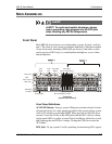
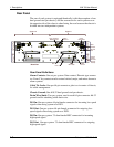
DSX Tracer Lamp: One per DSX jack; used to locate cross-connects.
ESD Jack: One per chassis. Used when performing maintenance to pre-
vent harmful electrostatic discharge to electronic components.
Fanning Strip: One row per wire-wrap pin field. Used to properly dress
cross-connect wires.
M13 Cards: One or two per system. Houses the active circuitry for multi-
plexing functions. One card for nonredundant systems, two cards for re-
dundant systems.
M13 Card Ejector Handle: One per M13 card. Used to remove and re-
place cards in the chassis.
Craft Port: One per system. Female DB-9, RS-232 serial connector used
to access the craft interface locally.
Wire-Wrap Pinfield: 28 DS1 pin fields per system. Used for routing and
cross-connecting DS1 signals. When using as a mux, Telect recommends
using these DS1 wire-wrap connections. This method of connecting the
low speed signals does not provide signal patching capabilities.
NOTE
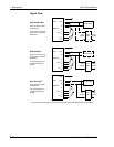
To use a system as a multiplexer with full DSX capabilities, connect incom-
ing and outgoing DS1 signals to the front wire-wrap pins.
LEDS
The LED status indicators on the MIX 56 front panel are grouped into the
following categories:
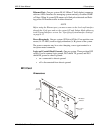
• DSX Tracer Lamps: When the tracer lamp (TL) pins of the cross-con-
nected modules are connected, the lamp lights when a plug is inserted
in the monitor port of one of the modules.
• M13 Card Status LED: One per card.
◊ Lights green for the active card.
◊ Lights orange for a standby card with no critical alarms.
◊ Solid red on the standby card indicates the card has detected a criti-
cal alarm condition or is otherwise nonoperational.
◊ Flashing red indicates a card cannot resolve an alarm condition.
◊ Unlit means the card is not receiving power, or has a failure in the
processor circuitry.
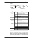
• LED Panel Indicators: See the next subsection.


