


360050398
Toshiba Corporation Digital Media Network Company
Page 116 of 157
© 2005, Copyright TOSHIBA Corporation All Rights Reserved
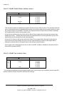
10.8.42.6.2.5 Device error count
The device error count field will contain the total number of errors attributable to the device that have been
reported by the device during the life of the device. These errors will include UNC errors, IDNF errors for
which the address requested was valid, servo errors, write fault errors, etc. This count will not include
errors attributed to the receipt of faulty commands such as commands codes not implemented by the
device or requests with invalid parameters or invalid addresses. If the maximum value for this field is
reached, the count will remain at the maximum value when additional errors are encountered and logged.
10.8.42.6.2.6 Data structure checksum
The data structure checksum is the two's complement of the sum of the first 511 bytes in the data structure.
Each byte will be added with unsigned arithmetic, and overflow will be ignored. The sum of all 512 bytes will be
zero when the checksum is correct. The checksum is placed in byte 511.
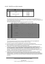
10.8.42.6.3 Comprehensive error log
The following defines the format of each of the sectors that comprise the SMART comprehensive error log. The
SMART Comprehensive error log provides logging for 28-bit addressing only. For 48-bit addressing see
10.8.43.2 . The size of the SMART comprehensive error log is 51 sectors. All multi-byte fields shown in this
structure follow the byte ordering described in 10.8.42.6.2.3 and 10.8.42.6.2.4. The comprehensive error log
data structures shall include UNC errors, IDNF errors for which the address requested was valid, servo errors,
write fault errors, etc. Comprehensive error log data structures shall not include errors attributed to the receipt of
faulty commands such as command codes not supported by the device or requests with invalid parameters or
invalid addresses.
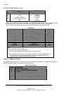
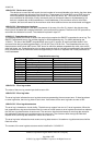
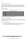
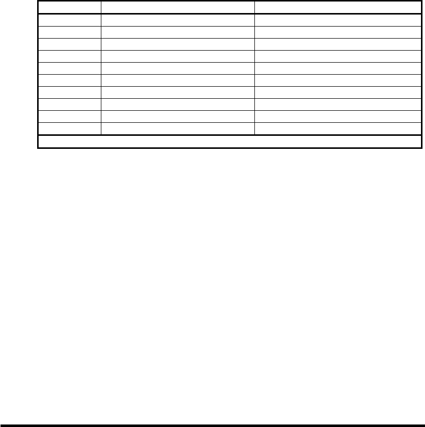
Comprehensive error log
Byte First sector Subsequent sectors
0 SMART error log version Reserved
1 Error log index Reserved
2-91 First error log data structure Data structure 5n+1
92-181 Second error log data structure Data structure 5n+2
182-271 Third error log data structure Data structure 5n+3
272-361 Fourth error log data structure Data structure 5n+4
362-451 Fifth error log data structure Data structure 5n+5
452-453 Device error count Reserved
454-510 Reserved Reserved
511 Data structure checksum Data structure checksum
n is the sector number within the log. The first sector is sector zero
10.8.42.6.3.1 Error log version
The value of the error log version byte shall be set to 01h.
10.8.42.6.3.2 Error log index
The error log index indicates the error log data structure representing the most recent error. If there have been
no error log entries, the error log index is set to zero. Valid values for the error log index are zero to 255.
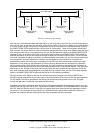
10.8.42.6.3.3 Error log data structure
The error log is viewed as a circular buffer. The device may support from two to 51 error log sectors. When the
last supported error log sector has been filled, the next error shall create an error log data structure that replaces
the first error log data structure in sector zero. The next error after that shall create an error log data structure
that replaces the second error log data structure in sector zero. The sixth error after the log has filled shall
replace the first error log data structure in sector one, and so on.
The error log index indicates the most recent error log data structure. Unused error log data structures shall be
filled with zeros.
The content of the error log data structure entries is defined in 10.8.42.6.2.2.