


360050398
Toshiba Corporation Digital Media Network Company
Page 56 of 157
© 2005, Copyright TOSHIBA Corporation All Rights Reserved
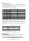
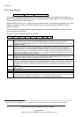
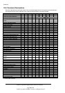
10.7.9 Status Register
-CS0 DA2-DA0:7 Read only
This register contains the command status. The contents of the register are updated at the completion of
each command and whenever the error occurs. The host system reads this register in order to acknowledge
the status and the result of each operation.
When the BSY bit (bit 7) is set, no other bits in the register are valid. And read/write operations of any other
register are negated in order to avoid the returning of the contents of this register instead of the other
resisters’ contents .
If the host reads this register when an interrupt is pending, interrupt request (INTRQ) is cleared in order to
work as Interrupt Acknowledge.
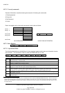
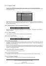
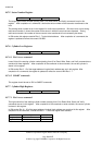
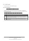
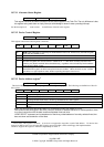
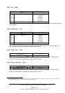
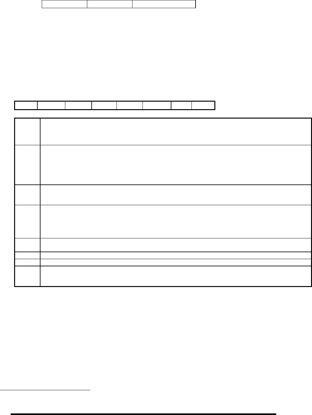
The bits of the status register are defined as below :
BSY DRDY DF DSC DRQ 0 0 ERR
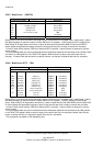
Bit 7
BSY (Busy) -- This bit is set when Host Reset (HRST) line is activated or Software Reset (SRST) bit in
Device Control register is set or when the COMMAND register is written and until a command is
completed but when Data Request is set to 1, this bit shall be reset. The host shouldn’t write or read any
registers when BSY = 1.
Bit 6
DRDY (Drive ready) -- DRDY=1 when seek complete bit (bit 4) = 1, indicates that the drive is ready to
respond read, write, or seek command. DRDY=0 indicates that read , write and seek are negated. A
command execution shall be interrupted if Not-Ready condition occurs during a command execution and
will be reset until the next command whether the drive condition is Ready or Not Ready. Error bit is set on
this occasion and will be reset just after power on and set again after the drive begins revolving at normal
speed and gets ready to receive a command.
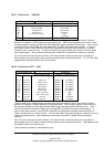
Bit 5
DF (Device Fault) -- DF=1 indicates that the drive has detected a fault condition during the execution of a
Read Write commands; read, write, and seek commands are negated and Error bit is set. DF is set to 1
until the next command, whether the device is in fault condition or not.
Bit 4
DSC
3
(Drive Seek Complete) – DSC³= 1 indicates that a seek operation has been completed. DSC³ is set
to 0 when a command accompanied by a seek operation begins. If a seek is not complete, a command is
terminated and this bit is not changed until the Status Register is read by the host . This bit remains reset
immediately after power on until the drive starts revolving at a nominal speed and gets ready to receive
command.
Bit 3
DRQ (Data Request) -- DRQ=1 indicates that the sector buffer requires 1 sector of data during a Read or
Write command.
Bit 2 Reserved
Bit 1 Reserved
Bit 0
ERR (Error) -- ERR = 1 indicates that an error occurred during execution of the previous command . The
cause of the error is reported on the other bit or in the error register. The error bit can be reset by the next
command from the controller. When this bit is set , a multi-sector operation is negated.
3
ATA-2 Notes: Prior to ATA-2 standard, this bit indicated that the device was on track. This bit may be used for other purposes in
future standards. For compatibility the drive supports this bit as ATA-1 specifies. User is recommended not to use this bit.