


4 Replacement Procedures
Figures
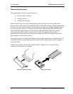
Figure 4-1 Removing the battery pack................................................................................. 4-8
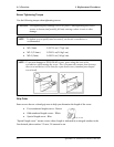
Figure 4-2 Removing the PC card ..................................................................................... 4-10
Figure 4-3 Removing the bridge media ............................................................................. 4-11
Figure 4-4 Removing the HDD assembly.......................................................................... 4-12
Figure 4-5 Removing the HDD.......................................................................................... 4-13
Figure 4-6 Removing the memory module........................................................................ 4-15
Figure 4-7 Removing the speaker cover assembly ............................................................ 4-17
Figure 4-8 Removing the keyboard ................................................................................... 4-18
Figure 4-9 Removing the keyboard support plate.............................................................. 4-19
Figure 4-10 Removing the bluetooth module...................................................................... 4-21
Figure 4-11 Removing the switch membrane...................................................................... 4-22
Figure 4-12 Removing the optical drive assembly .............................................................. 4-24
Figure 4-13 Disassembling the side bracket........................................................................ 4-25
Figure 4-14 Removing the screws (back)............................................................................ 4-26
Figure 4-15 Removing the screws (front)............................................................................ 4-27
Figure 4-16 Removing the cables ........................................................................................ 4-28
Figure 4-17 Removing the display assembly....................................................................... 4-29
Figure 4-18 Removing the wireless LAN antenna cables ................................................... 4-30
Figure 4-19 Removing the SD board................................................................................... 4-33
Figure 4-20 Removing the MDC......................................................................................... 4-34
Figure 4-21 Removing the fan ............................................................................................. 4-35
Figure 4-22 Removing the wireless LAN board.................................................................. 4-36
Figure 4-23 Removing the VGA fan cable.......................................................................... 4-37
Figure 4-24 Removing the system board............................................................................. 4-38
Figure 4-25 Removing the RTC battery .............................................................................. 4-40
Figure 4-26 Removing the TV tuner module....................................................................... 4-41
Figure 4-27 Removing the guide ......................................................................................... 4-43
Figure 4-28 Removing the heat sink.................................................................................... 4-44
Figure 4-29 Removing the CPU .......................................................................................... 4-45
QOSMIO F10 Maintenance Manual (960-498) 4-v