


4 Replacement Procedures 4.12 System board
4.12 System board
CAUTION: 1. When handling the system board, always hold by the edges. Do not touch
the printed circuit face.
2. If replacing with a new system board, execute the subtest01 Initial
configuration in section 3.3 “Setting of the hardware configuration”. Also
update with the latest BIOS as described in Appendix G “BIOS Rewrite
Procedures”.
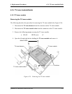
Removing the system board
The following describes the procedure for removing the system board (See Figure 4-23 and
4-24).
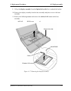
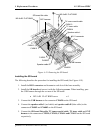
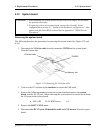
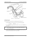
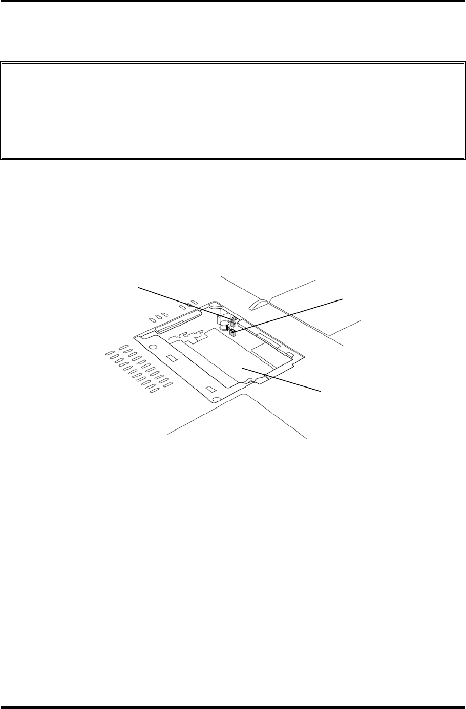
1. Disconnect the VGA fan cable from the connector CN8780 on the system board
from the bottom side.
VGA fan cable
CN8780
Memory slot
Figure 4-23 Removing the VGA fan cable
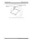
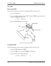
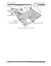
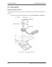
2. Turn over the PC and turn up the insulator to release the USB cable.
3. Remove the following screws securing the system board and remove the system
board with the DC-IN jack. When removing the system board, be careful not to break
the I/O ports on the system board.
• M2.5×4B FLAT BIND screw x4
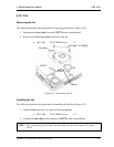
4. Remove the BATT CONN cover.
5. Disconnect the DC-IN jack, SD board flat cable and SVP harness from the system
board.
QOSMIO F10 Maintenance Manual (960-498) 4-37