


4.16 Cover assembly 4 Replacement Procedures
PORTEGE A100 Maintenance Manual (960-460) 4-33
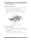
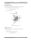
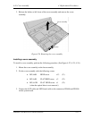
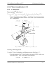
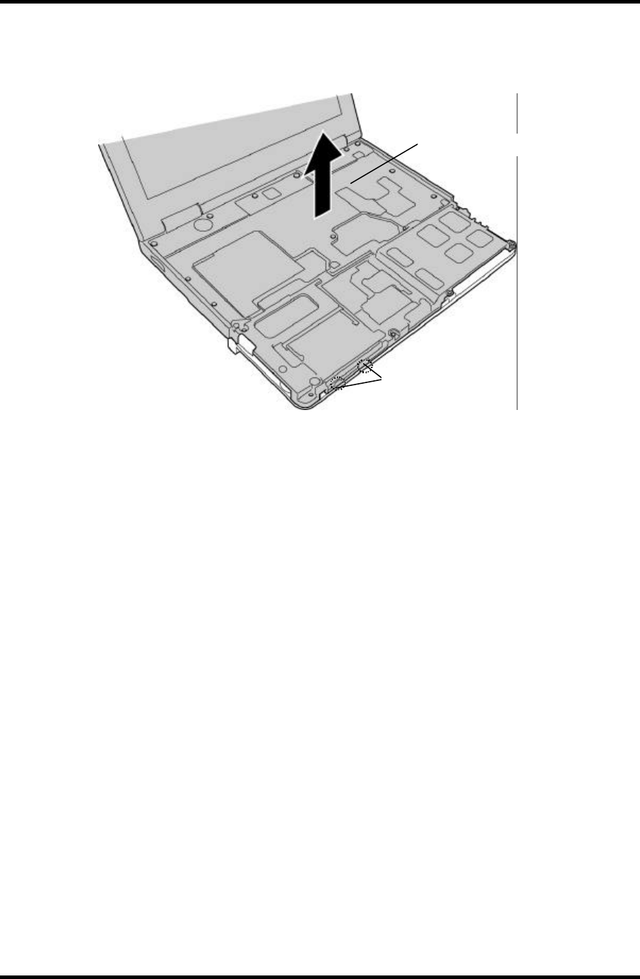
3. Release the latches at left lower of the cover assembly and remove the cover
assembly.
Cover assembly
Latches
Figure 4-24 Removing the cover assembly
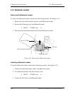
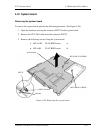
Installing a cover assembly
To install a cover assembly, perform the following procedure. (See Figure 4-22, 4-23, 4-24.)
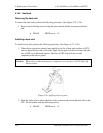
1. Mount the cover assembly on the base assembly.
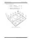
2. Fix the cover assembly with the following screws.
• M2.5×8B BIND screw x13 (•)
• M2.5×4B FLAT BIND screw x3 (‚)
• M2.5×12B FLAT BIND screw x1 (ƒ)
(when the optical drive is not removed.)
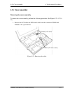
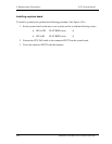
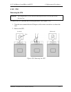
3. Connect the LCD cable and LED board cable to the connectors PJ5600 and PJ9500
on the system board.