


4 Replacement Procedures 4.19 2nd Battery board/Heat sink/CPU
4-38 PORTEGE A100 Maintenance Manual (960-460)
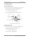
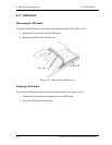
4.19.2 Heat sink
Removing the heat sink
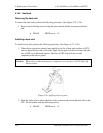
To remove the heat sink, perform the following procedure. (See Figure 4-27, 4-28.)
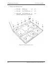
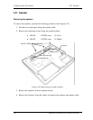
1. Remove the following screws fixing the heat sink and holder and remove the heat
sink.
• M2×4Z BIND screw x2
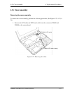
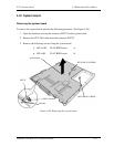
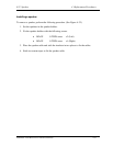
Installing a heat sink
To install a heat sink, perform the following procedure. (See Figure 4-27, 4-28.)
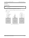
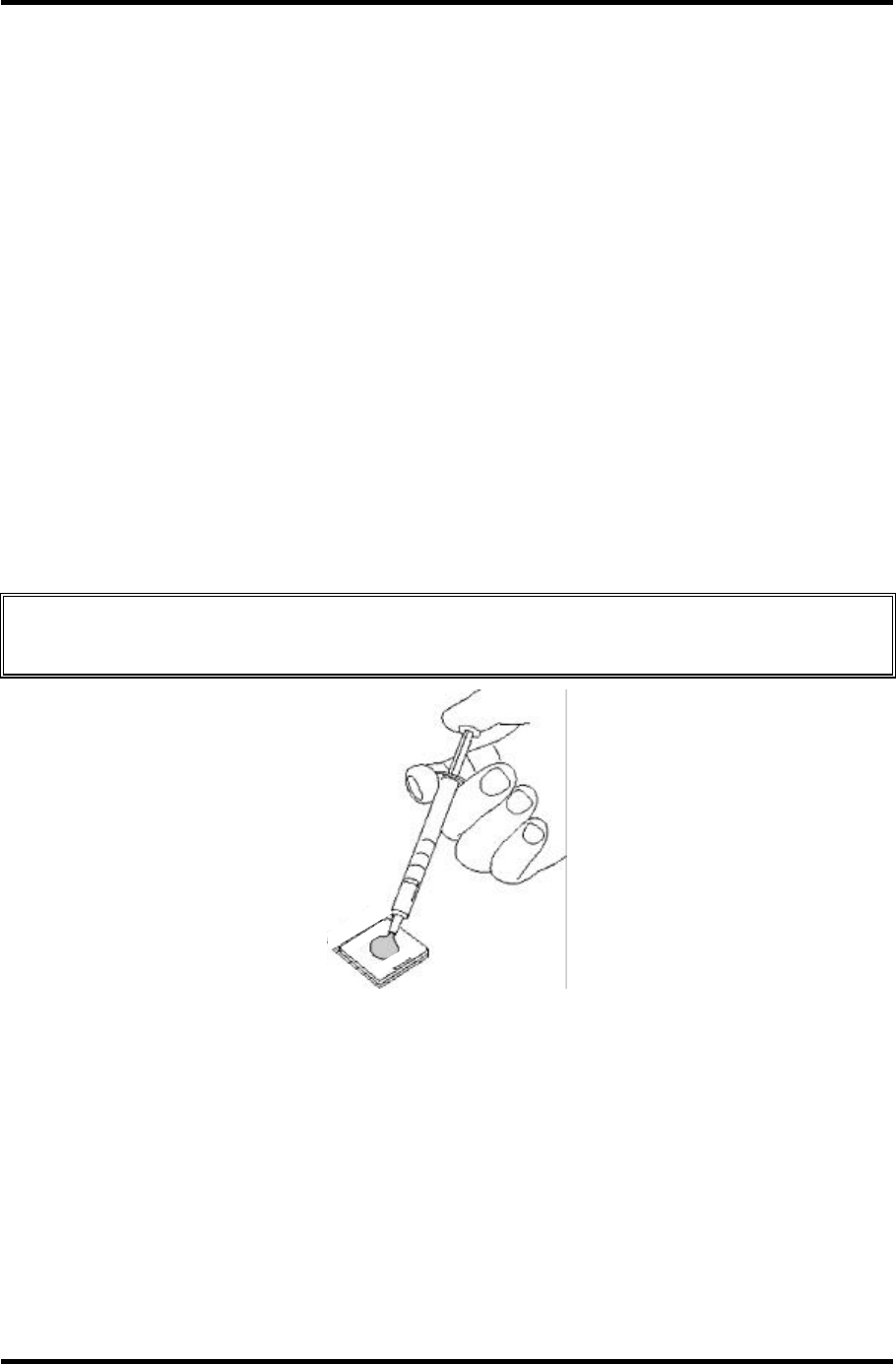
1. When silicon grease has already been applied to the fin of heat sink and face of CPU,
remove them cleanly with a soft cloth. Apply silicon grease to the fin of heat sink and
face of CPU by a dedicated injector. The face of CPU chip shall be covered
completely with silicon grease.
Caution: When using a dedicated injector, completely cover the face of CPU chip with
silicon grease.
Figure 4-28 Applying silicon grease
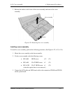
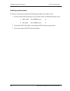
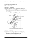
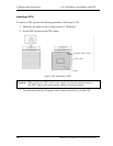
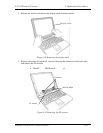
2. Hook the latch of heat sink to the hole of the system board and set the heat sink on the
CPU. Fix the holder with the following screws.
• M2×4Z BIND screw x2