


2.1 Troubleshooting 2 Troubleshooting Procedures
PORTEGE A100 Maintenance Manual (960-460) 2-1
2
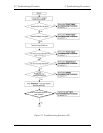
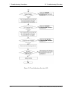
2.1 Troubleshooting
Chapter 2 describes how to determine which Field Replaceable Unit (FRU) in the computer is
causing the computer to malfunction. (The “FRU” means the replaceable unit in the field.)
The FRUs covered are:
1. Power supply 9. Modem
2. System Board 10. LAN
3. 3.5" USB FDD 11. Sound
4. 2.5" HDD 12. SC card slot
5. Keyboard 13. Wireless LAN
6. Display 14. Bluetooth
7. Optical Drive
8. Touch pad
The Detailed replacement procedures are given in Chapter 4. Test Program operations are
described in Chapter 3.
The following tools are necessary for implementing the Diagnostics procedures:
1. Diagnostics Disk (Test program for maintenance)
2. Phillips screwdrivers
Note: Be sure to use the PH point size “0” screwdriver complying with the ISO/DIS 8764-
1:1996. Use, however, the PH point size “1” screwdriver for screws fixing the
expansion memory slot cover and the keyboard.
3. Toshiba MS-DOS system FD
4. Work disk (for FDD testing)
5. Cleaning disk kit (for FDD head cleaning)
6. A set of tools for debug port test (test cable, test board, RS-232C cross cable, display,
D port FD)
7. PC with a serial port (for displaying debug port test result)
8. Wraparound connector for PC card
9. Tester
10. External CRT
11. External USB Keyboard
12. External USB mouse
13. Headphone
14. Microphone
15. TOSHJIBA CD-ROM test disk (ZA1217P01/P000204190)
16. Toshiba-EMI DVD-ROM TEST DISK TSD-1
17. Music CD
18. CD-RW media (Recommended media: RICHO, MITHUBISHI x 4 type)
19. DVD-ROM (in the market)
20. RJ-11 connector checker LED (Recommended media:
21. LAN wraparound connector