


2.15 Wireless LAN Troubleshooting 2 Troubleshooting Procedures
PORTEGE A100 Maintenance Manual (960-460) 2-49
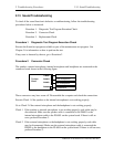
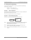
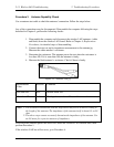
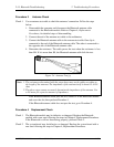
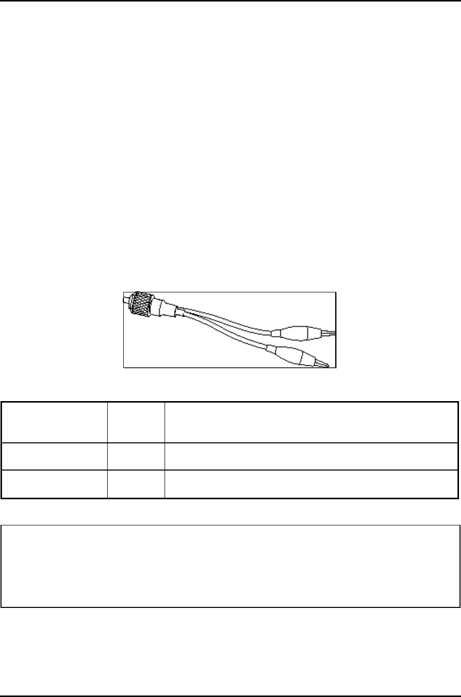
Procedure 3 Antenna Capability Check
Use an antenna test cable to check the antennas' connection. Follow the steps below.
Any of the connections may be disconnected. Disassemble the computer following the steps
described in Chapter 4, perform the following checks:
1. Disassemble the computer and disconnect the wireless LAN antennas (white
and black) from the wireless LAN board. Refer to Chapter 4, Replacement
Procedures, for detailed steps of disassembling.
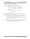
2. Connect the tester set up for impedance measurement to the antenna jig.
Measure the white antenna’s resistance.
3. Determine the resistance. The antenna passes the test when the resistance is
less than 5Ω. If it is more than 5Ω, the antenna is faulty.
4. Measure the black antenna’s resistance. Check if there is faulty.
Figure 2-3 Antenna Test jig
Measurement
Value
Pass/fail Comment
Less than 5Ω
Pass Include cable loss
More than 5Ω
Fail The digital tester shows 0L ,etc. if there is a broken wire.
Note: 1. The resistances determined with the steps above may not be stable according to
the length of the antenna. The impedance of the antenna itself is about 0.5 to 0.8
ohm.
2. The above steps cannot accurately determine the impedance of the antenna. Use
an LC meter for a precise measure of impedance.
If each wireless antenna passes the above test, return the Wireless LAN module back, then
perform Procedure 1.
If the wireless LAN has still an error, go to Procedure 4.