


4 Replacement Procedures
PORTEGE A200 Maintenance Manual (960-499) 4-v
Figure 4-15 Separating the HDD..................................................................................4-23
Figure 4-16 Removing the memory module ................................................................4-24
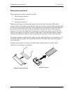
Figure 4-17 Removing the wireless LAN module .......................................................4-26
Figure 4-18 Removing the internal microphone ..........................................................4-27
Figure 4-19 Removing the MDC module.....................................................................4-28
Figure 4-20 Removing the speakers .............................................................................4-29
Figure 4-21 Removing the cables.................................................................................4-31
Figure 4-22 Removing the screws................................................................................4-32
Figure 4-23 Removing the screw .................................................................................4-33
Figure 4-24 Removing the cover assembly..................................................................4-33
Figure 4-25 Removing the RTC battery.......................................................................4-35
Figure 4-26 Removing the battery latch assembly.......................................................4-36
Figure 4-27 Removing the CPU fan.............................................................................4-37
Figure 4-28 Removing the SD board............................................................................4-38
Figure 4-29 Removing the system board......................................................................4-39
Figure 4-30 Removing the holder and heat sink ..........................................................4-40
Figure 4-31 Applying silicon grease ............................................................................4-41
Figure 4-32 Removing the CPU...................................................................................4-42
Figure 4-33 Installing a CPU........................................................................................4-43
Figure 4-34 Removing the screws and mask seals.......................................................4-44
Figure 4-35 Removing the display mask......................................................................4-45
Figure 4-36 Removing the FL inverter.........................................................................4-45
Figure 4-37 Removing the LED board.........................................................................4-46
Figure 4-38 Removing the screws................................................................................4-48
Figure 4-39 Removing the LCD unit............................................................................4-49
Figure 4-40 Removing the LCD support......................................................................4-50
Figure 4-41 Removing the hinge cap ...........................................................................4-51
Figure 4-42 Removing the LCD cable holder ..............................................................4-52
Figure 4-43 Removing the LCD cable .........................................................................4-52
Figure 4-44 Installing the LCD cable holder................................................................4-53
Figure 4-45 Removing the LED cable..........................................................................4-54
Figure 4-46 Removing the wireless LAN antenna .......................................................4-56