


1 Hardware Overview 1.6 Power Supply
1-16 PORTEGE A200 Maintenance Manual (960-499)
1.6 Power Supply
The power supply supplies 19 different voltages to the system board.
The power supply micro controller has the following functions.
1. Judges that the DC power supply (AC adapter) is connected to the computer.
2. Detects DC output and circuit malfunctions.
3. Controls the battery icon, and DC IN icon.
4. Turns the battery charging system on and off and detects a fully charged battery.
5. Turns the power supply on and off.
6. Provides more accurate detection of a low battery.
7. Calculates the remaining battery capacity.
8. Controls the transmission of the status signal of the main battery.
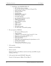
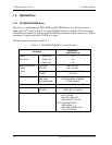
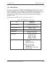
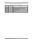
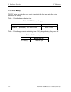
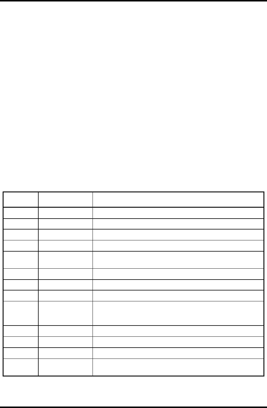
Table 1-6 lists the power supply output specifications.
Table 1-6 Power supply output specifications(1/2)
Name Voltage [V] Use
PPV 1.308-0.748 CPU,GMCH, ICH4-M
PTV 1.05 CPU, GMCH, ICH4-M
1R35-P1V 1.35 GMCH
1R25-P1V 1.25 DDR-SDRAM termination
MR1R25-
B1V
1.25
GMCH, DDR-SDRAM
1R5-P1V 1.5 TV, GMCH, IVH4-M
1R5-S1V 1.5 ICH4-M
2R5-B2V 2.5 GMCH, DDR-SDRAM
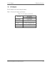
P3V 3.3
Clock Generator, Thermal Sensor, GMCH, SDRAM(SPD), TV,
IEEE1394, ICH4-M, AD1981B, mini-PCI, EC/KBC, LCD,
SD card Power, KINNERTH
E3V 3.3 YEBISUSS, PC Card Power, mini-PCI, MDC
BT-P3V 3.3 Bluetooth
S3V 3.3 ICH4-M, EC/KBC, Flash Memory, PSC
P5V 5
CRT, ICH4-M, FL inverter, LEDs, HDD, ODD, KB, PAD,
Bluetooth Power