


6-11
EM18-33010A
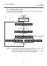
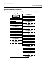
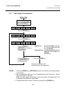
6. DIAG. TEST OPERATION
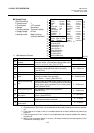
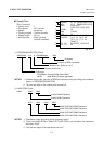
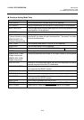
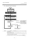
DIP SW
DIP Switch 1
0: OFF (OPEN)
1: ON (SHORT)
DIP Switch 2
0: OFF (OPEN)
1: ON (SHORT)
Pin No.
00000000
87654321
10001010
87654321
Status
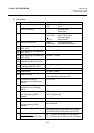
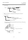
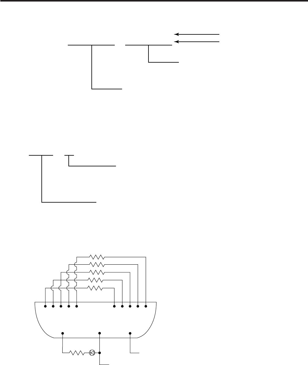
EXP. I/O
Expansion I/O PC board
Loopback test
OK: The circuit has no problem.
NG: The circuit has a problem or loopback jig
is not attached.
OK
Connector: FCN-781P024-G/P
Fig. 6-3
For the loopback test, connect jig as shown below and check HIGH output / HIGH input and
LOW output / LOW input.
(Revision Date Jan. 13, ’95)
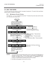
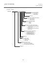
6.2 SELF TEST MODE
8 DIP SW Check
NOTE: The DIP switch 1-7 is to be set to 0 (OFF:OPEN) regardless of setting item.
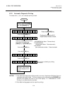
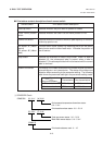
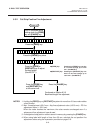
9 EXP. I/O Check
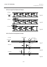
1 2 3 4 5 7 8 9 10 11
300Ω x 5
12
15
300Ω
Vcc
GND
21