


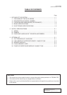
1-2
1. OUTLINE OF THE SYSTEM
EM10-33006A
1.3 OVERVIEW AND DIMENSIONS (APPROXIMATE)
POWER
ON LINE
ERROR
FEED RESTART PAUSE
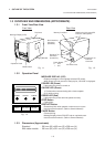
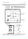
1.3 OVERVIEW AND DIMENSIONS (APPROXIMATE)
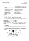
1.3.1 Front View/Rear View
Front View Rear View
Message Display (LCD)
Operation Panel
Media Outlet
Fig. 1-1
Fig. 1-2
AC Power Inlet
Power Switch
O : OFF
I:ON
Expansion I/O
Interface
Connector
Serial Interface
Connector
(RS-232C)
Parallel I/F
Connector
(Centronics)
Supply Window
Top Cover
Outlet for the high speed PC
interface cable (Option)
Memory Card Slot
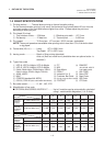
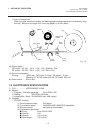
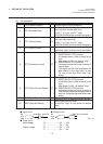
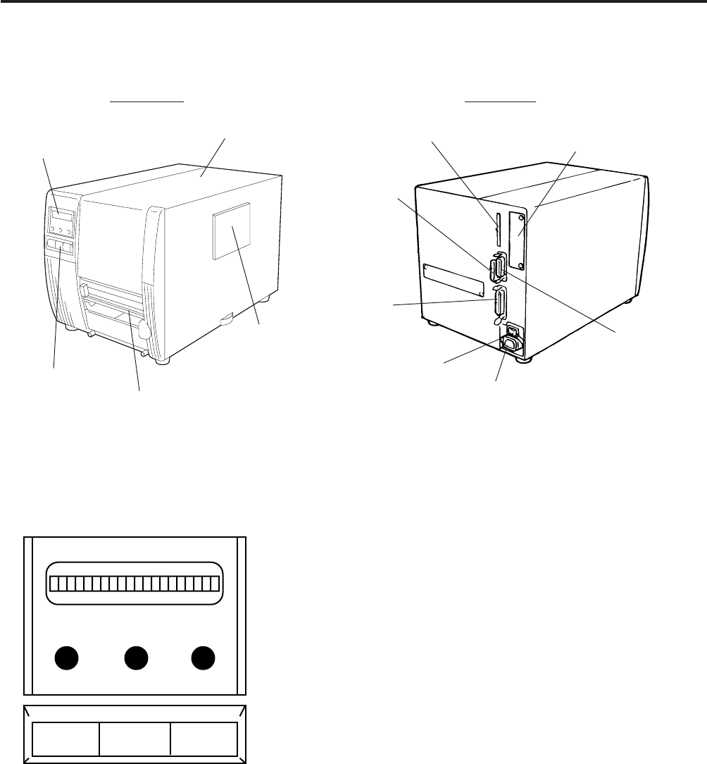
1.3.2 Operation Panel
MESSAGE DISPLAY (LCD)
Displays messages in the language selected DIP switch.
When power is turned on and it is ready to print, "ON LINE" is displayed.
POWER LED (Green)
Lights when the power is turned on.
ON-LINE LED (Green)
1) Flashes when communicating with a host computer.
2) On while printing.
ERROR LED (Red)
Lights when the printer does not operate correctly.
FEED Button
Feeds paper.
RESTART Button
Resets the printer when paused or when an error occurs.
Used to set the threshold. (Refer to Owner's Manual)
PAUSE Button
Pauses printing.
Message display shows "PAUSE" and an unprinted count.
Used to set the threshold. (Refer to Owner's Manual)
Fig. 1-3
1.3.3 Dimensions (Approximate)
Standard : 291 mm (W) x 460 mm (D) x 308 mm (H)
With cutter module : 291 mm (W) x 521 mm (D) x 308 mm (H)