


2-3
EM18-33010A
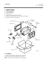
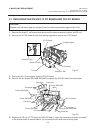
2. MAJOR UNIT REPLACEMENT
CAUTION:
Be careful when replacing the CPU PC board, since a non-resettable counter (IC12) is installed on
this board. (Refer to Section 6.2.1 Maintenance Counter Printing.)
If this counter should be reset, replace IC12.
Fig. 2-4
Fig. 2-5
(Revision Date: Feb. 10, 2000)
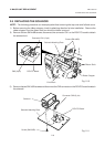
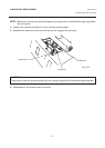
2.1 REPLACING THE PS UNIT, I/F PC BOARD AND CPU PC BOARD
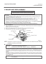
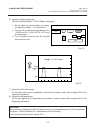
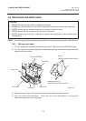
6) Adjust the ribbon end sensor.
Use the following Ribbons; TTM-78 (Maker: Fujicopian)
1 Set the ribbon so that the ribbon end sensor
can detect the ribbon. Turn the power on.
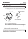
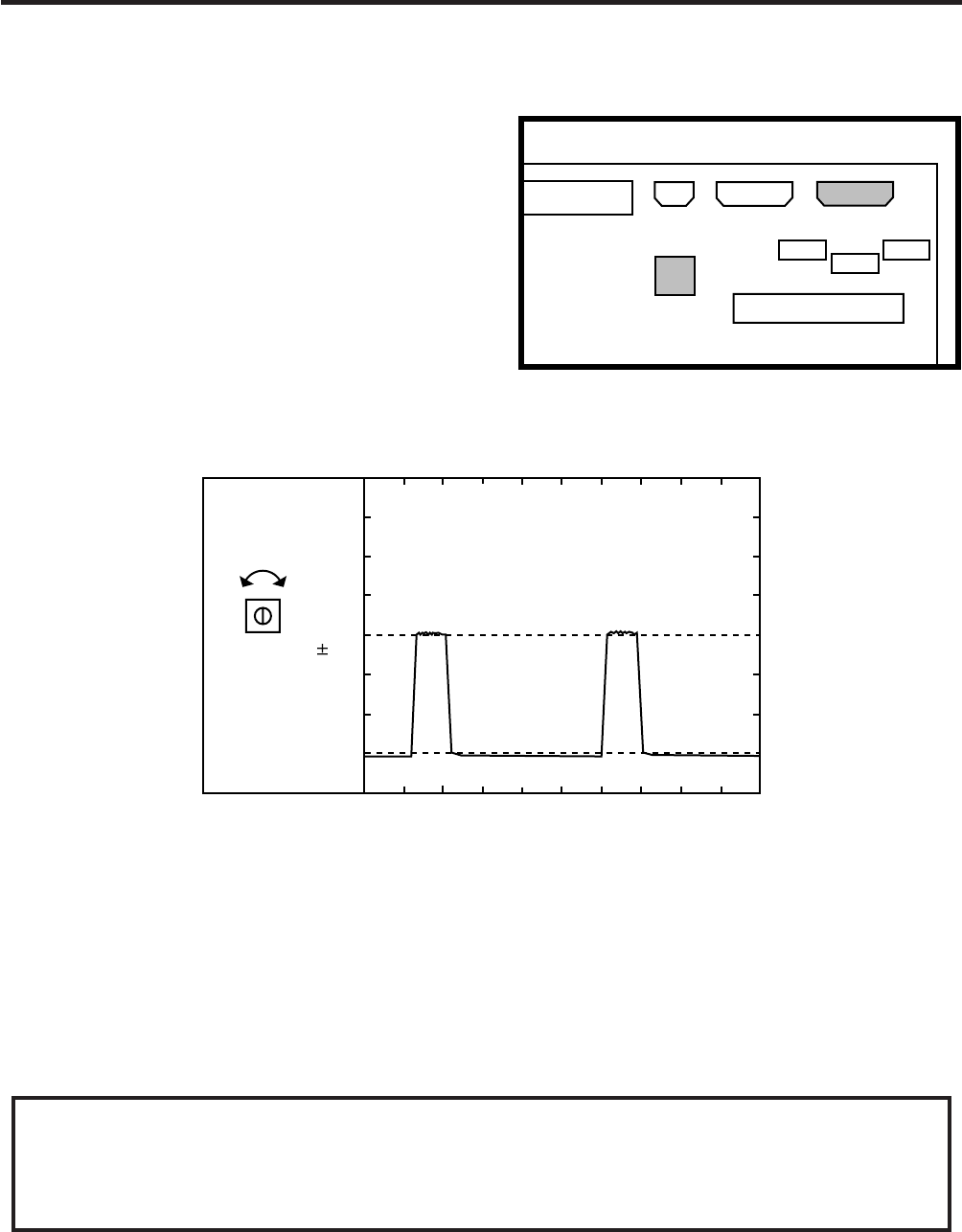
2 Turn the VR1 so that the voltage between Pin
1 (GND) and Pin 7 of CN12 is 3.0 ± 0.2 V with
an oscilloscope.
3 Turn the power off and mount the left side
cover and top cover.
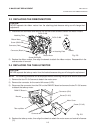
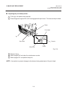
7) Adjust the black mark sensor.
As the black mark sensor is adjusted by key entries in system mode, refer to page 6-39 for the
adjustment procedure.
8) Adjust the feed gap sensor.
As the feed gap sensor is adjusted by key entries in system mode, refer to page 6-40 for the
adjustment procedure.
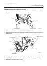
CN7
CN8 CN9
VR1
CN10
113
CN12
IC28
IC25
IC23
Range : 1V / 0.2 m sec.
Voltage
3.0
0.2V
VR1
GND