


2-8
EM18-33010A
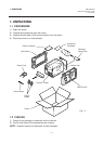
2. MAJOR UNIT REPLACEMENT
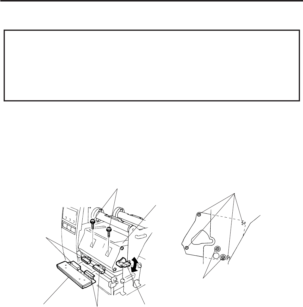
Fig. 2-13
(Revision Date Feb. 01, ’96)
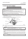
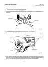
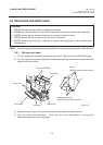
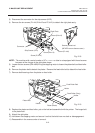
2.6 REPLACING THE PRINT HEAD
2.6 REPLACING THE PRINT HEAD
CAUTION:
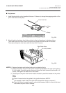
1. NEVER touch the element when handling the print head.
2. NEVER touch the connector pins to avoid a breakdown of the print head by static electricity.
3. NEVER remove the two screws painted red on the side of the print block.
4. NEVER remove the four screws on the side of the print block.
5. NEVER remove the print block, otherwise it requires the adjustment of the position when
reassembling.
NOTE: The following procedure can be employed without removing the top cover and the left side cover.
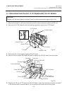
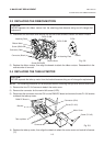
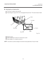
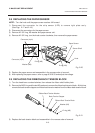
2.6.1 Old type print head
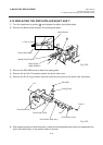
1) Turn the head lever clockwise to lower the print head. Remove the two SM-4x8B screws.
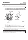
2) Turn the head lever counter clockwise and disconnect the two connectors to detach the print
head from the print block.
3) Replace the print head, connect the connectors and install it in the print block.
4) Turn the head lever clockwise. Push the print head and secure it temporarily.
Follow the procedure on the next page.
Screw (SM-4x8B)
Screws
(NEVER remove these screws.)
Screws painted red
(NEVER remove these screws.)
Connector
Print Block
Print Head
Connector
Head Lever