


2-11
EM18-33010A
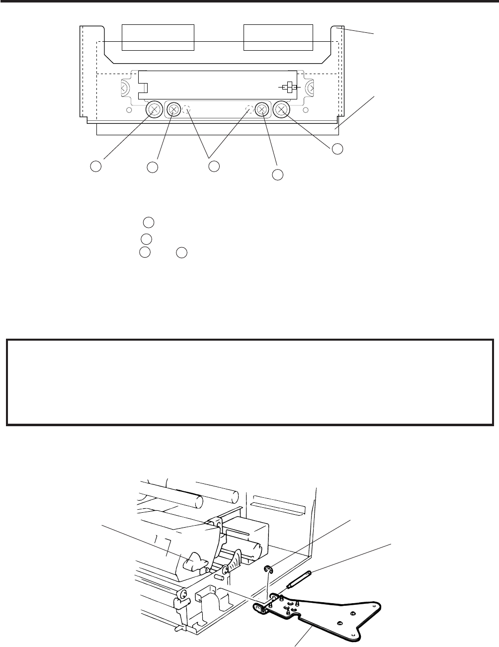
2. MAJOR UNIT REPLACEMENT
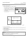
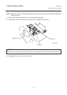
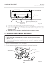
Fig. 2-17
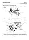
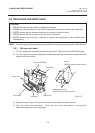
2.6 REPLACING THE PRINT HEAD
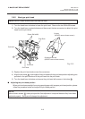
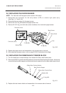
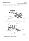
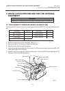
2.7 REPLACING THE PLATEN AND FEED ROLLER
1) Remove the front plate and belt cover. (See Fig. 2-6.)
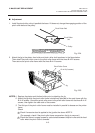
2) Turn the head lever counterclockwise, then release the ribbon shaft holder plate.
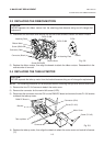
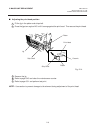
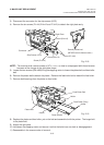
Fig. 2-16
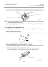
(1) Loosen the screws c securing the print head position adjusting pin.
(2) Loosen the screws b one by one, slightly move the print head backward or forward, and then
tighten the screws b and c . Ensure that the print head is parallel to the platen. If not, print
tone will be uneven.
(3) Make a test print and if necessary, repeat Step 2) until the printer prints properly.
CAUTION:
1. NEVER remove the four screws painted red fixing the right plate and reinforcing plate.
(See Fig. 2-16)
2. The pinch roller belt assembled inside the printer does not need to be replaced because it
receives less load.
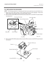
Print Head Bracket
Print Head
b (securing the print head)
c (securing the adjusting pin)
A
(Print Head Position
Adjusting Pin)
cb
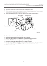
E-ring (M3)
Hold Shaft
Ribbon Shaft Holder Plate
Head Lever