


3-2
EM18-33010A
3. INSTALLATION PROCEDURE FOR THE OPTIONAL EQUIPMENT
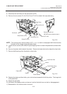
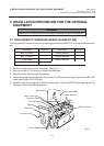
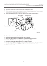
9. Reassemble in the reverse order of removal.
10. Following procedure should be employed with your PC after this.
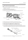
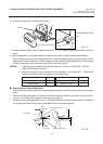
11. Set the DIP SW. on the BPC PC board for the I/O address according to your PC.
12. Install the BPC PC board on the expansion port bus line of your PC.
13. Connect the printer cable mentioned in step 5 to the BPC PC board.
14. Insert the attached FDK into the FDD and install the data in the hard disk. Since the installation
procedure is different between MS-DOS and Windows, refer to each owner’s manual.
15. Perform a motion check.
Fig. 3-2
(Revision Date: Feb. 10, 2000)
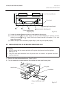
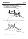
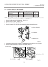
3.1 HIGH SPEED PC INTERFACE BOARD (B-4800-PC-QM)
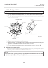
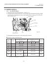
6. Connect the printer cable to the connector (CN1) on the BPE PC board.
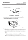
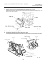
7. Put the cable strain relief of the printer cable in the notch of the cable support plate. Secure the cable
strain relief to the cable support plate by turning the nut.
8. Attach the cable support plate to the printer with the FL3x5 screws removed in step 2.
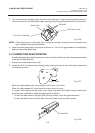
Connector (CN1)
BPE PC Board
Printer Cable
Cable Support
Screw (FL-3x5)
Nut
Cable Strain Relief