


3-5
EM18-33010A
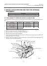
3. INSTALLATION PROCEDURE FOR THE OPTIONAL EQUIPMENT
Fig. 3-8
(Revision Date Aug. 11, ’95)
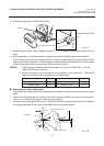
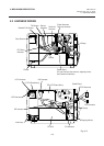
3.2 CUTTER MODULE (B-4205-QM)
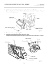
■ Adjusting the Cutter Guide Plates
After replacing the cutter unit the following adjusting procedure should be employed to prevent paper
jams.
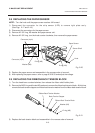
1. Attach the cutter guide plate A with two SM-4x6C screws so that the fixed cutter is positioned 0.1
mm to 0.4 mm above the bottom of the cutter guide plate A.
2. Attach the cutter guide plate B with two FL-4x8 screws so that there is a clearance of 0.5 mm between
the cutter guide plate A and cutter guide plate B using a clearance gauge.
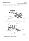
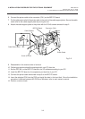
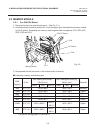
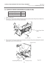
10. Mount the cutter cover with the two screws.
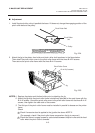
11. Reassemble the motor cover, rewind full sensor (Tr), I/F PC board, left side cover and top cover in
order.
12. After reassembly is complete, perform a test print to confirm that the cutter works properly.
After printing a print sample at a speed of 8”/sec., feed the media about 33 mm and check that the
swing cutter works without error. After cutting the media, feed the media about 33 mm in the reverse
direction and check that it correctly stops at the print start position.
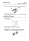
NOTES: 1. If the top edge of label winds onto the platen in cut issue, set DIP SW. 1-5 to ON.
(Refer to the Owner’s Manual.)
2. Retain the parts that are removed during installation of the cutter unit. They will be
required when the printer is modified to a standard type.
Fig. 3-7
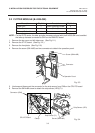
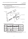
Removed Parts
Front plate
Black screws
Q’ty/Unit
1
2
Q’ty/Unit
1
2
Removed Parts
Strip sensor (LED)/(Tr)
Screw (P-4x6)
Cutter Cover
Screw
Cutter Attaching Screw
Cutter Guide Plate A
Screw
(SM-4x6C)
0.1 - 0.4 mm
0.5 mm
Cutter Guide Plate B
Screw
(FL-4x8)
Fixed Cutter