


3-7
EM18-33010A
3. INSTALLATION PROCEDURE FOR THE OPTIONAL EQUIPMENT
(Revision Date: Feb. 10, 2000)
3.3 MEMORY MODULE
3.3.2 For New CPU PC Board
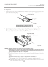
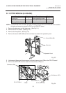
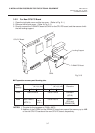
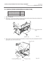
1. Open the right side cover and the top cover. (Refer to Fig. 2-1.)
2. Remove the left side cover. (Refer to Fig. 2-1.)
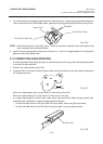
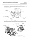
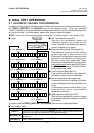
3. Directly connect the D-RAM PC board to CN16 on the CPU PC board, and then secure it with
the two locking support.
Fig. 3-10
D-RAM PC Board
CN16
CPU PC Board
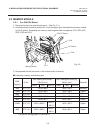
■ Expansion memory and drawing size
NOTES: 1.
The size for the tag paper is 79.68 x 997.0
2. Addition of the D-RAM and the DRAM PC board can expand the memory up to 4MB
of the old CPU PC board and the new CPU PC board, respectively.
RAM
Capacity
2MB
4MB
138.0 x 640.0
138.0 x 995.0
(NOTE 1)
Max. drawing size (normal)
(W) x (H) (mm)
Batch
Strip Auto-cut
138.0 x 320.0
130.8 x 661.3
Max. drawing size (on-the-fly)
(W) x (H) (mm)
Remarks
Standard
((IC19)
Option
(IC19 and
DRAM PCB)
Batch
Strip Auto-cut
138.0 x
991.0
(NOTE 1)
Locking Support