E658130
- 7 -
4. Installation on inverter
Refer to VF-S15 option adapter instruction manual (E6581838) for the installation on the
inverter.
Mandatory
The following steps must be performed before installing.
1. Shut off all input power.
2. Wait at least 15 minutes and check to make sure that the charge lamp is no longer lit.
4.1. Connection cable
In the CC-Link system, use CC-Link dedicated cables.
If the cable used is other than the CC-Link dedicated cable, the performance of the
CC-Link system is not guaranteed.
For the specifications of the CC-Link dedicated cable, refer to the website of the CC-Link
Partner Association.
Website: http://www.cc-link.org/
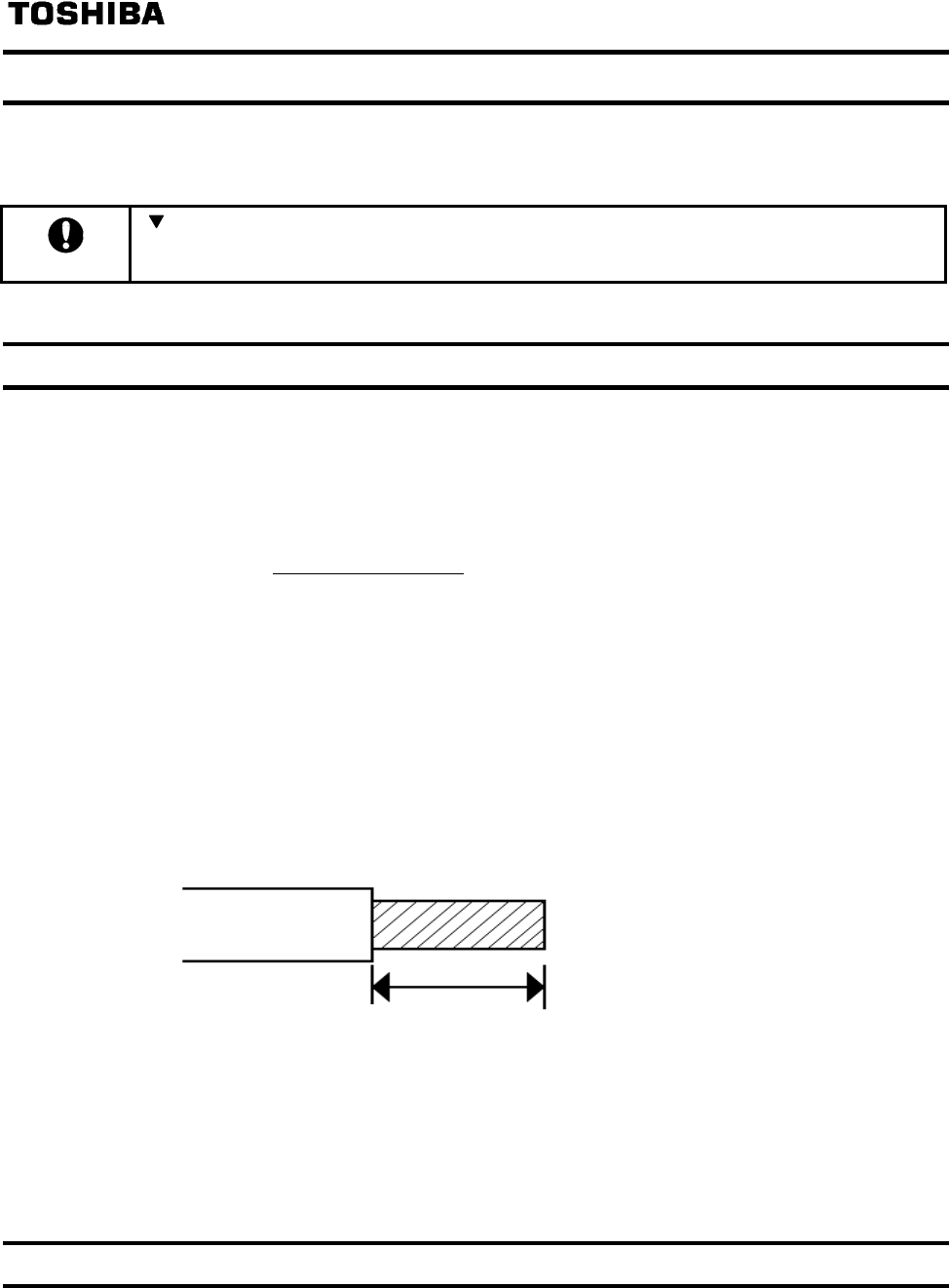
Strip off the sheath of the CC-Link dedicated cable and wind wires to use. If the length of
the sheath pealed is too long, a short circuit may occur among neighboring wires. If the
length is too short, wires might come off.
・Recommended screwdriver:Small flat-blade screwdriver
(Tip thickness: 0.4mm /tip width: 2.5mm)
・Recommented tightening Torque:0.22N・m to 0.25N・m
・Cable stripping size:About 7mm
7mm
*Fix a cable so that a communication connector may be not taken the weight of wire.
When the cable is not connected easily, the use of the following bar terminal is
recommended.
Phoenix Contact Co. Ltd.
Bar terminal model:
AI-TWIN2x0,5-8 WH
Length of bar terminal: 8mm
4.2. Terminating resistor
Connect the terminating resistor of 110Ω or 130Ω (CC-Link Ver.1.00 dedicated high
performance cable.) between terminals at the end.


