


TMP92CZ26A
92CZ26A-223
3.10.2 Operation Description
(1) Memory access control
The SDRAMC is enabled by setting SDACR<SMAC> to “1”.
When one of the bus masters (CPU, LCDC, DMAC) generates a cycle to access the SDRAM
address area, the SDRAMC outputs SDRAM control signals.
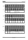
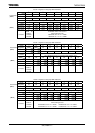
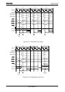
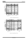
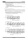
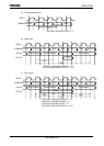
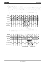
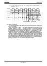
Figure3.10.2 to Figure3.10.5 shows the timing for accessing the SDRAM. The number of
SDRAM access cycles is controlled by the SDRAMC and does not depend on the number of
waits controlled by the memory controller.
(a) Command issue function
The SDRAMC issues commands as specified by the SDCMM register. The SDRAMC also
issues commands automatically for each SDRAM access cycle generated by each bus
master.
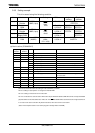
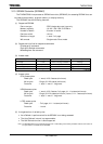
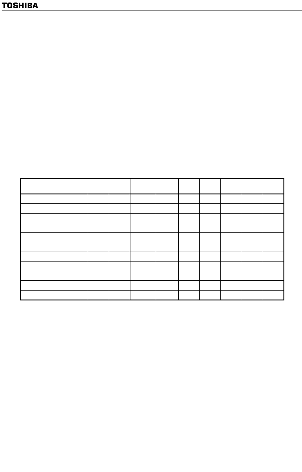
Table 3.10.1 shows the commands that are issued by the SDRAMC.
Table 3.10.1 Commands Issued by the SDRAMC
Command CKE
n-1
CKE
n
SDxxDQM A10
A15-11
A9-0
SDCS SDRAS SDCAS SDWE
Bank Activate H H H RA RA L L H H
Precharge All H H H H X L L H L
Read H H L L CA L H L H
Read with Auto Precharge H H L H CA L H L H
Write H H L L CA L H L L
Write with Auto Precharge H H L H CA L H L L
Mode Register Set H H H L M L L L L
Burst Stop H H H X X L H H L
Auto Refresh H H H X X L L L H
Self Refresh Entry H L H X X L L L H
Self Refresh Exit L H H X X H H H H
Note 1: H = High level, L = Low level, RA = Row address, CA = Column address, M = Mode data, X = Don’t care
Note 2: CKE
n
= CKE level in the command input cycle
CKE
n-1
= CKE level in a cycle immediately before the command input cycle