


TMP92CZ26A
92CZ26A-315
3.14 Serial Channels (SIO)
TMP92CZ26A includes 1 serial I/O channel (SIO0). For both channels either UART mode
(Asynchronous transmission) or I/O interface mode (Synchronous transmission) can be selected.
And, SIO0 includes data modulator that supports the IrDA 1.0 infrared data communication
specification.
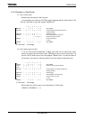
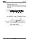
In mode 1 and mode 2, a parity bit can be added. Mode 3 has a wakeup function for making
the master controller start slave controllers via a serial link (A multi-controller system).
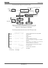
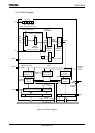
Figure 3.14.1 is block diagrams for each channel.
SIO0 is compounded mainly prescaler, serial clock generation circuit, receiving buffer and
control circuit, transmission buffer and control circuit.
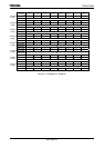
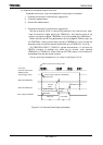
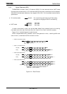
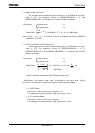
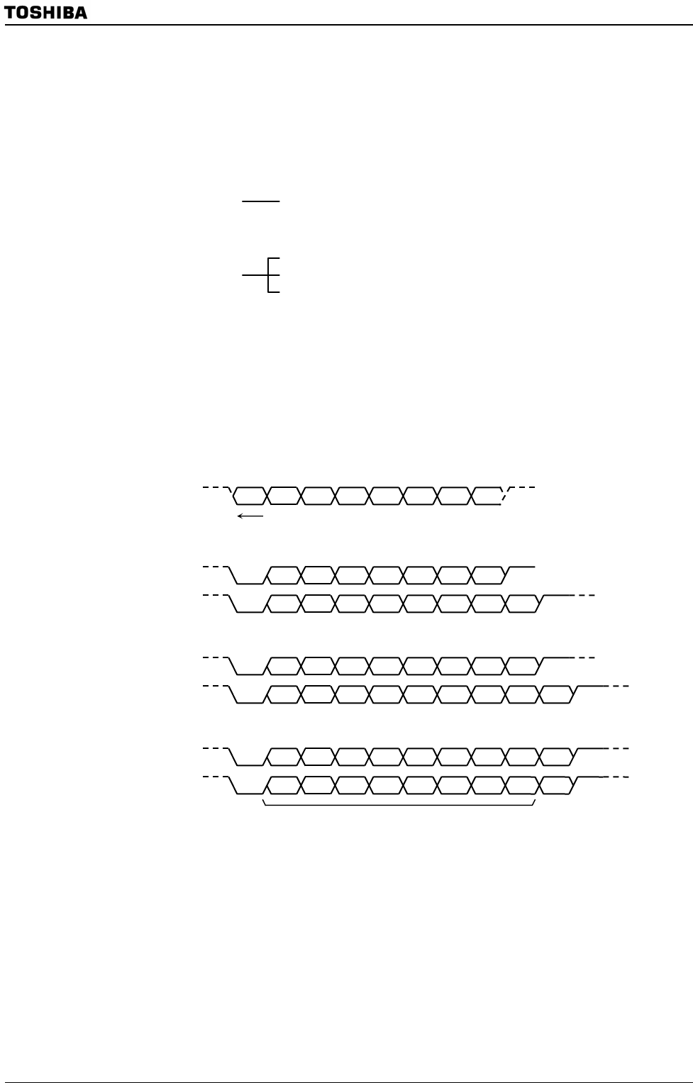
Figure 3.14.1 Data Formats
• I/O interface mode
Mode 0: For transmitting and receiving I/O data using
the synchronizing signal SCLK for extending
• UART mode
Mode 1: 7-bit data
Mode 2: 8-bit data
Mode 3: 9-bit data
Bit0
1 2 3 4 5 6 7
Bit0
1 2 3 4 5 6 Stop
Start
Bit0
1 2 3 4 5 Parity
Stop
Start
6
Bit0
1 2 3 4 5 7
Stop
Start
Bit0
1 2 3 4 5 Parity
Stop
Start
7
6
6
Bit0
1 2 3 4 5 8
Stop
Start
Bit0
1 2 3 4 5 Stop
Start
Bit8
6
6
7
7
Transfer direction
• Mode 0 (I/O interface mode)
• Mode 1 (7-bit UART mode)
No parity
Parity
No parity
Parity
• Mode 2 (8-bit UART mode)
• Mode 3 (9-bit UART mode)
When bit8 = 1, Address (Select code) is denoted.
When bit8 = 0, Data is denoted.
Wakeup