


TMP92CZ26A
92CZ26A-427
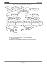
(c) Control transfer type
Control transfer type is configured in below three stages.
• Setup stage
• Data stage
• Status stage
Data stage is skipped sometimes. Each stage is configured in one or plural
transaction. UDC executes each transaction while managing of three stages in
hardware. Control transfer type has below 3 type by whether there is data stage
or not, or direction.
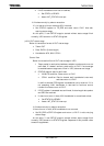
• Control read transfer type
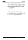
• Control write transfer type
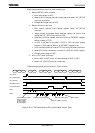
• Control write transfer type (Not data stage)
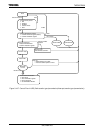
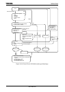
3-transfer sequences are shown in
Figure 3.16.10, Figure 3.16.11 and Figure
3.16.12.
UDC answers automatically about standard request in hardware. Class request,
vendor request have to intervening CPU on controlling UDC.
Below is control flow in UDC and control flow in intervening CPU.
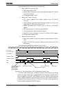
(c-1) Setup stage
Setup stage is same with transmission bulk transaction except case of token ID
become to SETUP.
However, control flow in UDC differ it.
• Token: SETUP
• Data: DATA 0
• Handshake: ACK
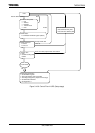
Control flow
Below is control flow in UDC when SETUP token is received.
1. SETUP token packet is received and address, endpoint number and error
are confirmed. And it checks whether applicable endpoint is the control
transfer mode.
2. STATUS register state is confirmed.
State return to IDLE only it is INVALID state.
In bulk transfer mode, receiving data is enabled by STATUS registers value
and FIFO condition. However, in SETUP stage, STATUS is returned to
READY and accessing from CPU to FIFO is prohibited always, and internal
FIFO of endpoint 0 is cleared. And it prepares for following dataphase.
If CPU accesses Setup Received registers in UDC, it recognizes as Device
request is received, and accessing from CPU to EP0 is enabled.
There is this function for receiving it if new request is received in during
present device request is not finishing normally.