


MR-3018/3020/3021/3022 © 2005 - 2011 TOSHIBA TEC CORPORATION All rights reserved
DESCRIPTION OF OPERATIONS
3 - 18
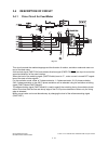
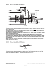
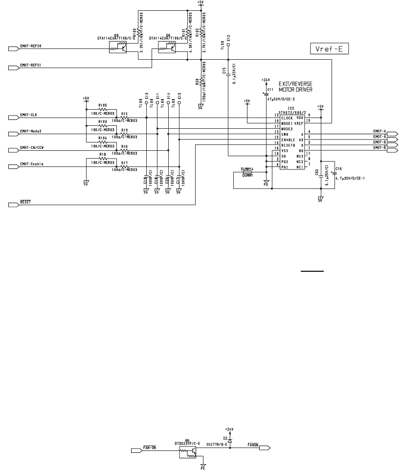
3.4.3 Drive Circuit for Exit Motor
Fig. 3-8
This circuit controls the rotation/stoppage and the direction of rotation, excitation mode and motor cur-
rent of the exit motor.
A drive clock signal (EMOT-CLK) and rotation direction signal (EMOT-CW/CCW
) are input to control
the speed and direction of the motor rotation.
When the level of the enabling signal (EMOT-Enable) is set to "L", motor current is turned OFF regard-
less of the state of other signals.
As IC3-10pin (MODE1) is connected to +5V, excitation mode is applied at 1-2 phase excitation.
The edge switching signal (EMOT-Mode3) is used to specify the switching timing for excitation phase
either from when both the rise and decay edge of the CLK input are detected or when only the rising
edge is detected.
Motor current value can be set discretionary by switching the level of the reference switching signal
(EMOT-REFS0,EMOT-REFS1).
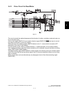
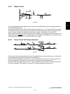
3.4.4 Drive Circuit for FAN Motor
Fig. 3-9
This circuit controls the rotation/stoppage of the fan motor. The FAN starts to rotate when the FAN
motor drive signal level is set to “H”, and stops when the level is set to “L”.