4.5 WLAN Card 4 Replacement Procedures
NB250/NB255 Maintenance Manual 4-35
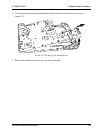
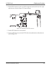
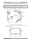
4. Put the DC IN connector in the lower DC IN trough and route the cable from left to right
under the ribs as shown in Figure 4.25. Fasten with tape.
Figure 4.25 Installing the DC IN connector
5. Seat the DC IN plate in its correct position.
6. Secure two M2.5x4 screws and attach FAN cable to the motherboard as indicated by the
arrow in Figure 4.20.


