4.21 VGA PCB 4 Replacement Procedures
4.21 CRT PCB
Removing the CRT PCB
To remove the CRT PCB, first remove the battery pack, keyboard, display assembly, and top
cover, then follows the steps below:
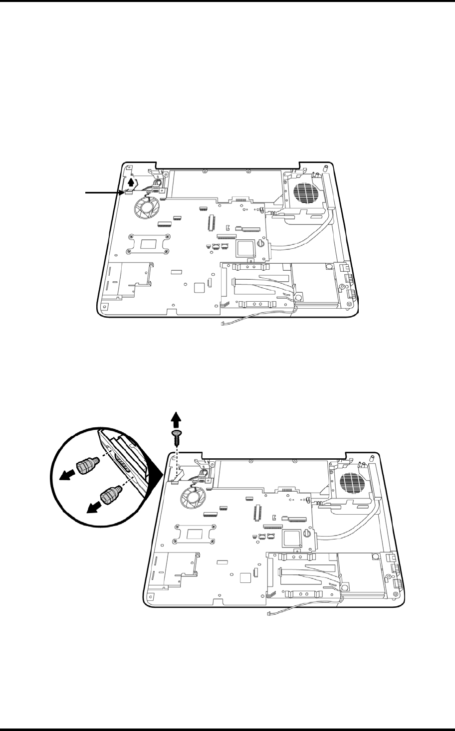
1. Disconnect the CRT PCB wire cable (JP24) from the system board.
JP24
Figure 4-61 Removing the CRT PCB FFC cable
2. Remove the M2x6 screw securing the CRT PCB. Then remove the two hexagonal CRT
screws from the left side of the computer.
Figure 4-62 Removing the CRT PCB screw and the hexagonal screws
Satellite P200D/P205D Series Maintenance Manual
[CONFIDENTIAL]
4-53


